Modbus RTU PWM Output 4CH
| SKU | Product |
|---|---|
| 33921 | Modbus RTU PWM Output 4CH |
Features
- Output uses high-speed opto-isolation; output high-level voltage can be selected via internal jumper
- Four independent PWM pulse outputs with adjustable frequency and duty cycle
- Supports setting device address (1 - 255) for cascading multiple devices via RS485 bus
- Onboard voltage regulator chip supports wide 7 V - 36 V power supply
- Onboard integrated isolated power supply provides stable isolated voltage; the isolated side requires no additional power
- Onboard integrated magnetic coupling isolation provides signal isolation, ensuring high reliability and strong anti-interference capability
- Onboard resettable fuse and TVS (transient voltage suppression) diode effectively suppress surge voltage and transient spike voltage in the circuit, providing overcurrent, overvoltage, lightning, and electrostatic protection
- Built-in watchdog timer ensures stable operation without freezing
- Rail-mounted enclosure design, compact size, easy installation
- Three external LED indicators for easy monitoring of power status and signal transmission/reception
Product Parameters
| Communication Interface | RS485 |
|---|---|
| Communication Baud Rate | 4800, 9600, 19200, 38400, 57600, 115200, 128000, 256000 |
| Default Communication Format | 9600, N, 8, 1 |
| Modbus Protocol | Standard Modbus RTU protocol |
| Supply Voltage | DC 7 - 36 V |
| Output Voltage | 3.3 V or 5 V selectable |
| Output Current | < 30mA, signal type |
| Pulse Frequency | 1 Hz - 200 kHz |
| Pulse Resolution | 0.01 Hz |
| Pulse Accuracy | 5‰ |
| Duty Cycle | 0 - 100% |
| Duty Cycle Resolution | 0.01% |
| Duty Cycle Accuracy | 5‰(1 Hz - 50 kHz), 1%(50 kHz - 200 kHz) |
LED Indicator Descriptions
| Indicator | Status Description |
|---|---|
| PWR LED | Power indicator, flashes when MCU is working normally |
| TXD LED | Transmission indicator, lights up when transmitting data |
| RXD LED | Reception indicator, lights up when receiving data |
Hardware Interface Description
D1 - D4 are pulse output terminals, GND is power ground. The PWM output frequency range is 1 Hz - 200 kHz.

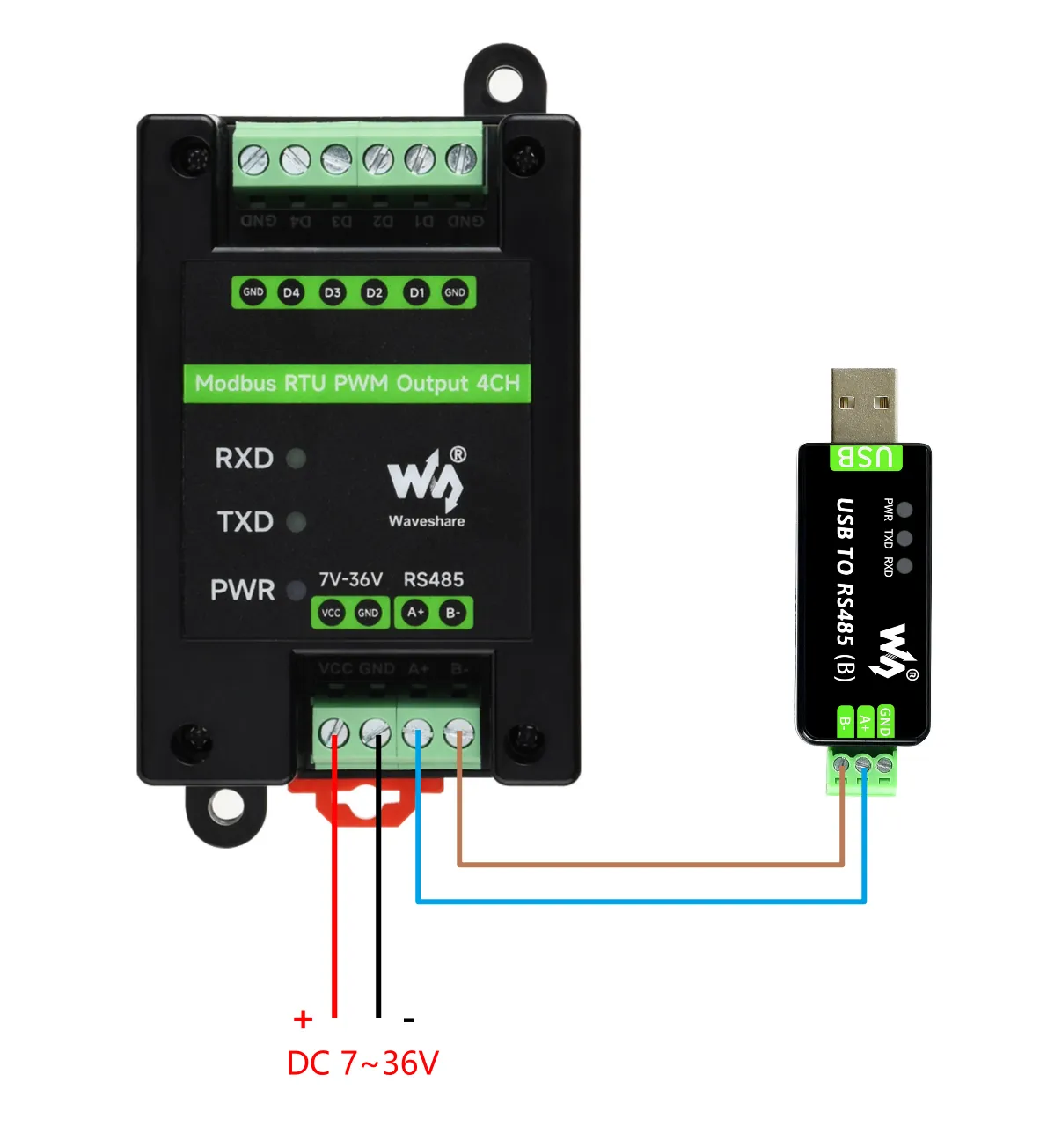
Hardware Connection Description
Connect the USB TO 485 converter to the target board using jumper wires, connecting A-->A and B-->B as shown in the figure below: