Example
This chapter explains how to download, configure, and run the C, Python, STM32, and Arduino examples for controlling the 4-channel PWM output module via Modbus RTU.
This product is a finished functional module, not a development board. Firmware source code and project files for the module are not provided.
The C, Python, STM32, and Arduino examples provided on this page are for demonstration purposes only, showing how an external host can operate the module via Modbus RTU. They are not part of the module's source code.
Host board adaptation, hardware troubleshooting, and user-modified GPIO/UART initialization code are not within the scope of example program support.
Download the Example
Ubuntu users can install the download and extraction tools, then download the example archive.
sudo apt install -y wget unzip
wget https://files.waveshare.com/wiki/Modbus_RTU_PWM_Output_4CH/Pwm_4ch.zip
unzip pwm_4ch.zip
cd pwm_4ch
The extracted directory structure is as follows:
pwm_4ch/
├── c/
├── python/
├── STM32/
└── Arduino/
Windows users can download the example using a browser, extract it, and then navigate to the corresponding platform directory.
Feature Overview
The device has 4 PWM channels, numbered 1 - 4. The example library provides the following functions:
| Function | C, STM32 | Python | Arduino | Modbus Command |
|---|---|---|---|---|
| Read or set single-channel frequency | read_frequency, write_frequency | read_frequency(), write_frequency() | readFrequency(), writeFrequency() | Read 0x03, Write 0x10 |
| Read or set single-channel duty cycle | read_duty, write_duty | read_duty(), write_duty() | readDuty(), writeDuty() | Read 0x03, Write 0x06 |
| Read and write frequency and duty cycle for one channel simultaneously | read_channel, write_channel | read_channel(), write_channel() | readChannel(), writeChannel() | Read 0x03, Write 0x10 |
| Read and write multiple channels | read_channels, write_channels | read_channels(), write_channels() | readChannels(), writeChannels() | Read 0x03, Write 0x10 |
| Read or set serial parameters | read_serial_param, write_serial_param | read_serial_parameters(), write_serial_parameters() | readSerialParameters(), writeSerialParameters() | Read 0x03, Write 0x06 |
| Read or set device address | read_address, write_address | read_device_address(), write_device_address() | readDeviceAddress(), writeDeviceAddress() | Read 0x03, Write 0x06 |
| Read software version | read_version | read_software_version() | readSoftwareVersion() | Read 0x03 |
Python Example
The Python example is located in the python/ directory and uses pymodbus for Modbus RTU communication. It is recommended to install dependencies in a virtual environment:
sudo apt install -y python3 python3-venv python3-pip
cd python
python3 -m venv .venv
source .venv/bin/activate
python -m pip install pymodbus
Open main_pwm4ch.py and modify the serial port and device address according to your actual connection. The default serial port in the example is /dev/ttyUSB0:
SERIAL_PORT = "/dev/ttyUSB0"
The main operations in the example are as follows:
# Initialize the serial bus and the PWM device separately; multiple devices can be connected to the same bus.
client = ModbusSerialClient(
    port=SERIAL_PORT,
    baudrate=9600,
    bytesize=8,
    parity="N",
    stopbits=1,
    timeout=0.3,
)
bus = ModbusRtuBus(client)
bus.connect()
pwm = ModbusRtuPwmOutput4Ch(device_id=1)

# Read CH1 frequency and duty cycle
value = pwm.read_channel(bus, 1)

# Set CH1 to 1000 Hz, 50%
pwm.write_channel(bus, 1, 1000.0, 50.0)

# Set both CH1 and CH2
pwm.write_channels(bus, 1, [(1000.0, 50.0), (200.0, 20.0)])

# Read CH1 - CH2
values = pwm.read_channels(bus, 1, 2)
Run the full example:
python main_pwm4ch.py
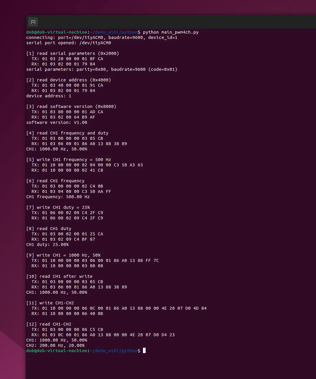
Below is the actual output of the Python example on Ubuntu:
C Example
The C example is located in the c/ directory:
pwm4ch.h: Data structures, error codes, and public interface declarations.pwm4ch.c: Modbus RTU frame assembly, CRC calculation, response parsing, and device operation implementation.main_pwm4ch.c: A complete calling example that prints the TX and RX frames for each communication.Makefile: Build, run, and clean commands.
Before running, modify PWM4CH_DEMO_PORT in main_pwm4ch.c. On Linux, set it to /dev/ttyUSB0 or /dev/ttyACM0; on Windows, set it to the actual port name such as COM6. The example does not accept command-line arguments, so you must rerun make after any changes.
pwm4ch_bus_t bus;
pwm4ch_t pwm;

/* Open the serial port and initialize the device with address 1. */
pwm4ch_bus_open(&bus, "/dev/ttyUSB0", 9600);
pwm4ch_init(&pwm, 1);

/* Set CH1 to 1000 Hz, 50%. */
pwm.write_channel(&pwm, &bus, 1, 1000.0, 50.0);

/* Read back CH1; the result is stored in pwm.channel[0]. */
pwm.read_channel(&pwm, &bus, 1);

pwm4ch_bus_close(&bus);
Compile with:
sudo apt install -y build-essential
cd c
make
./pwm4ch_demo
On Windows with MSYS2/MinGW, run:
cd c
mingw32-make
./pwm4ch_demo.exe
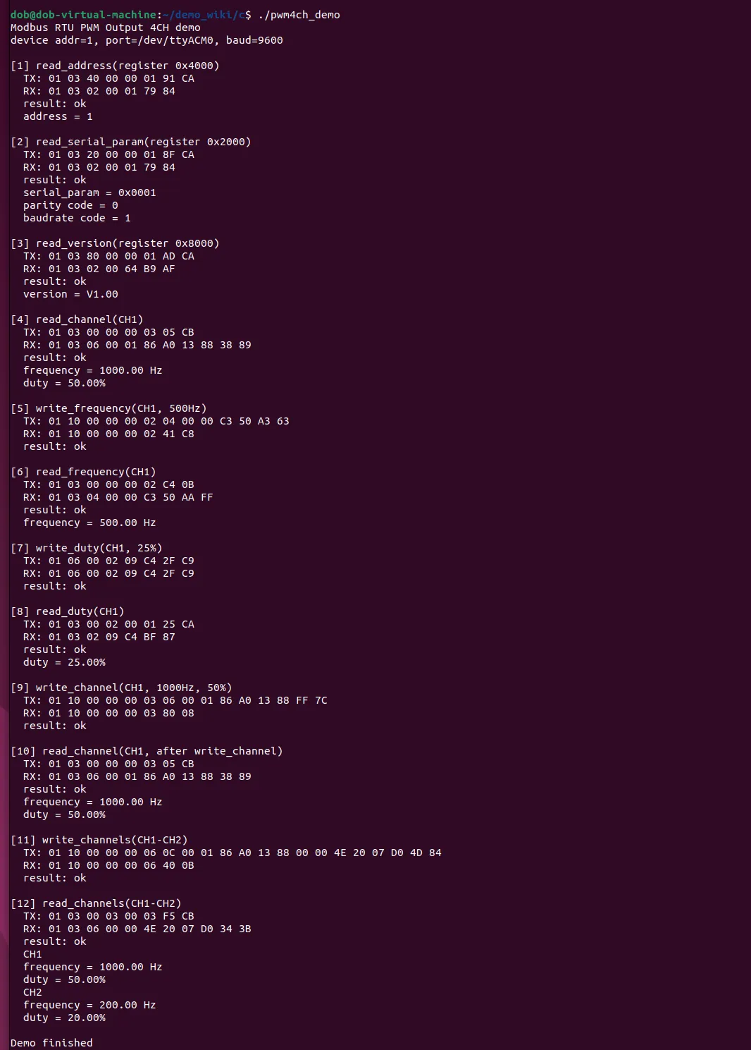
The C example saves and prints the last transmitted frame tx, received frame rx, and Modbus exception codes, making it easy to verify device address, function code, register, and CRC.
STM32 Example
Hardware used: NUCLEO-F103RB and RS485 CAN Shield.
The STM32 example is located in the STM32/ directory. The Keil project MDK-ARM/Modbus PWM 4CH.uvprojx already includes Src/pwm4ch.c and Inc/pwm4ch.h.
Use Keil MDK to compile and flash:
- Double-click to open
STM32/MDK-ARM/Modbus PWM 4CH.uvprojx. - In Keil, select the target
Modbus PWM 4CHand clickRebuildto recompile the project. - Connect the programmer and click
Downloadto flash the program.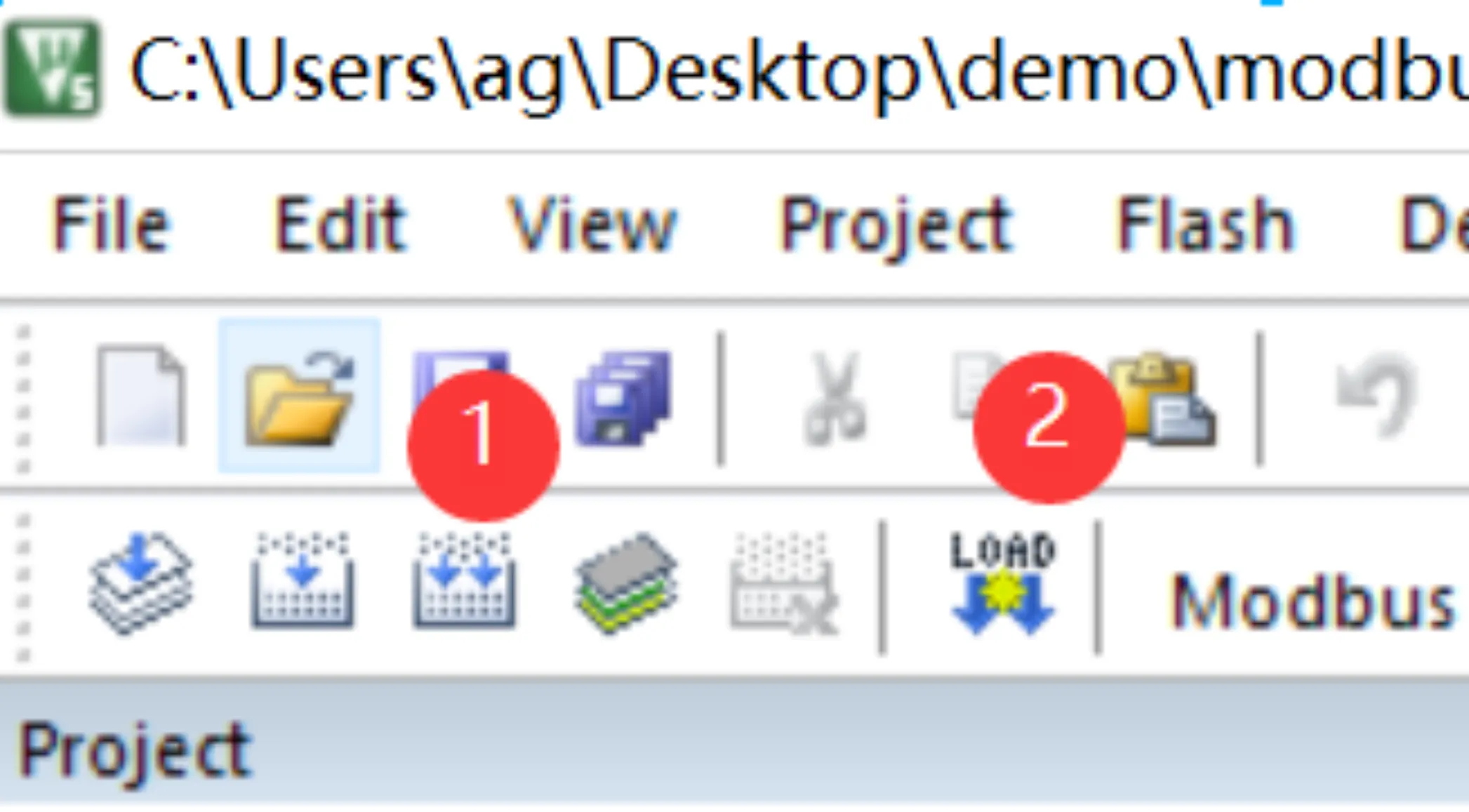
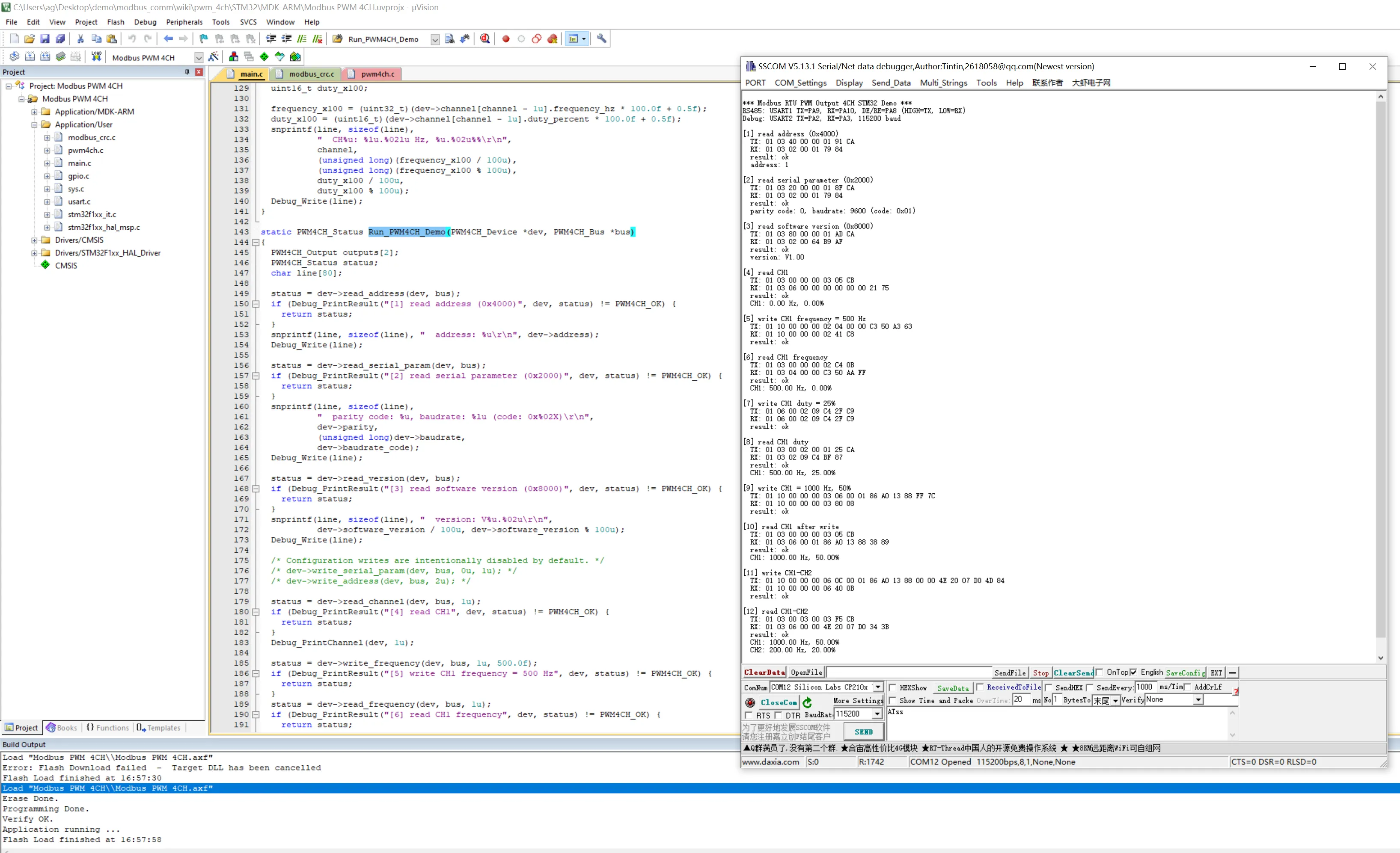
- Use the SSCOM serial debug assistant to open the USART2 debug serial port with settings
115200, 8N1. - Reset the board and view the device operations, TX, RX, and results.
The RS485 and debug serial pins in the example project are as follows:
| Channel | STM32F103 Pin | Connection or Purpose |
|---|---|---|
| RS485 Transmit | PA9 / USART1_TX | Connect to RS485 transceiver DI |
| RS485 Receive | PA10 / USART1_RX | Connect to RS485 transceiver RO |
| RS485 Direction Enable | PA8 / GPIO Output | Connect to both DE and /RE; high for transmit, low for receive |
| Debug Serial Transmit | PA2 / USART2_TX | Connect to serial tool RX; outputs TX, RX frames and results |
| Debug Serial Receive | PA3 / USART2_RX | Initialized in the example; not used for debug commands in this demonstration |
Device function call example:
PWM4CH_Bus pwm_bus;
PWM4CH_Device pwm;

PWM4CH_Init(&pwm, 1);

pwm.write_channel(&pwm, &pwm_bus, 1, 1000.0f, 50.0f);
pwm.read_channel(&pwm, &pwm_bus, 1);
After reset, the program sequentially reads and writes device address, serial parameters, software version, and PWM channels via the USART2 debug serial port.
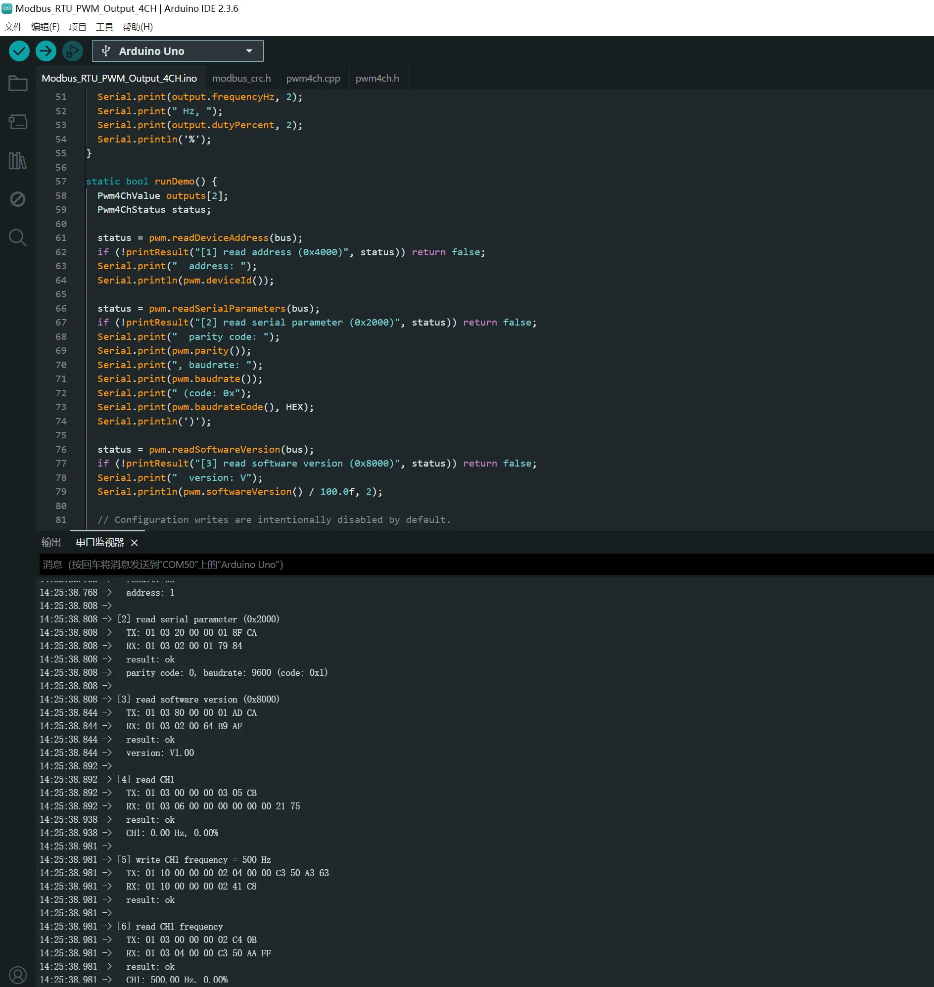
Arduino Example
Hardware used: UNO PLUS and RS485 CAN Shield.
Compile and upload using the Arduino IDE:
-
Double-click to open
Arduino/Modbus_RTU_PWM_Output_4CH/Modbus_RTU_PWM_Output_4CH.ino. -
In the Arduino IDE, select the board
Arduino Unoand the corresponding serial port. -
Click
Verifyto compile the example. -
After compilation, click
Uploadto upload the program to the UNO PLUS. -
After upload completes, open the Arduino IDE
Serial Monitorand set the baud rate to115200. -
Reset the board and view the device operations, TX, RX, and results.

Device function call example:
SoftwareSerial rs485(2, 8);   // RX, TX
ModbusRtuBus bus(rs485, 7);   // Serial port and RS485 transceiver
ModbusRtuPwmOutput4Ch pwm(1); // PWM device address

pwm.writeChannel(bus, 1, 1000.0f, 50.0f);
pwm.readChannel(bus, 1);

const Pwm4ChValue &value = pwm.value(1);
The full example prints TX and RX frames for each communication by default. To disable printing, comment out #define PWM4CH_PRINT_FRAMES at the beginning of the .ino file.
Precautions
- After changing the device address or serial parameters, subsequent communications must use the new parameters.
- If communication fails, check power supply, RS485 A/B wiring, serial port permissions, device address, and baud rate in order.