PocketTerm35 Assembly Guide
Pre-Assembled Version Notes
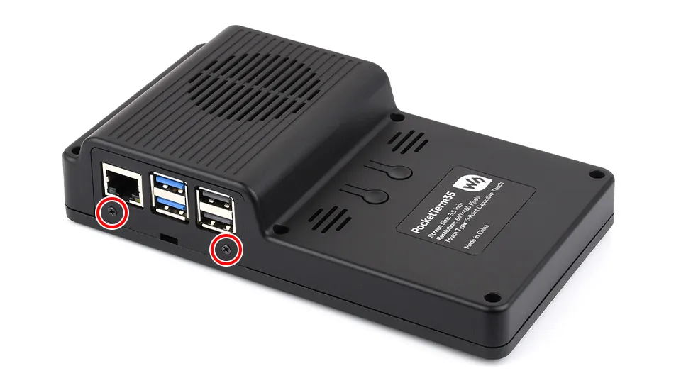
If you purchased the PocketTerm35-Pi4 or PocketTerm35-Pi5 pre-assembled version, the device comes fully assembled with the system pre-installed. No assembly steps are required below.
Simply press the top power button to power on and start using it. Default login credentials:
- Username:
pi - Password:
raspberry
Video Assembly Tutorial
Assembly Preparation
Please check the accessories list to ensure everything is complete before starting assembly.
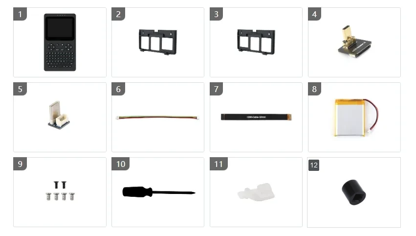
Assembly Steps
- If a side panel is already installed, remove it first.
- Before disassembly or assembly, remove the TF card to avoid damaging the card or the slot.
- Upon receiving the product, please first check the appearance of the battery. If you find swelling, damage, leakage, or any other abnormality, do not power on the device and contact after-sales support promptly.
Step 1: Remove the Back Cover
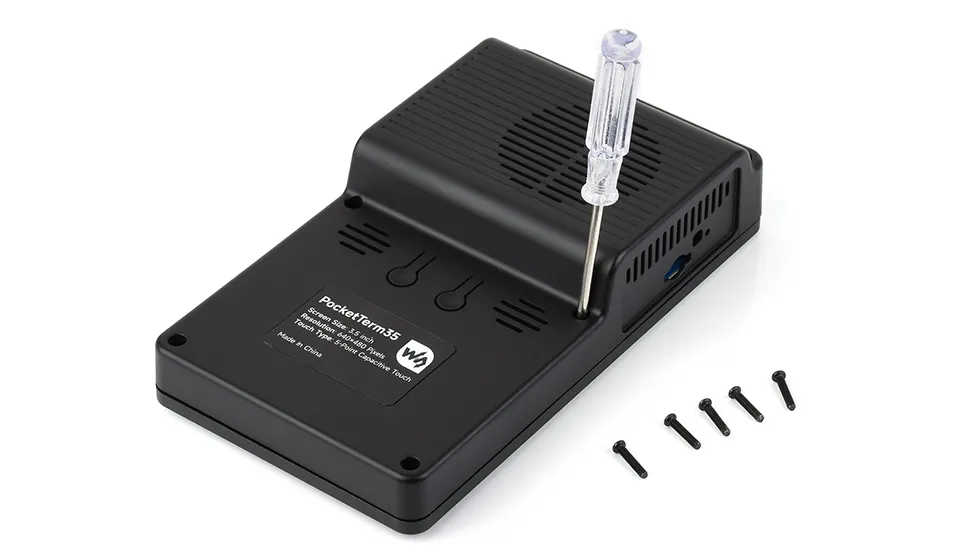
Unscrew the 6 PM2.5×12 black screws, then lift the back cover upward from the bottom and remove it.
When removing the back cover, do not pull forcibly to avoid damaging internal cables or connectors.
Step 2: Assemble the Cables
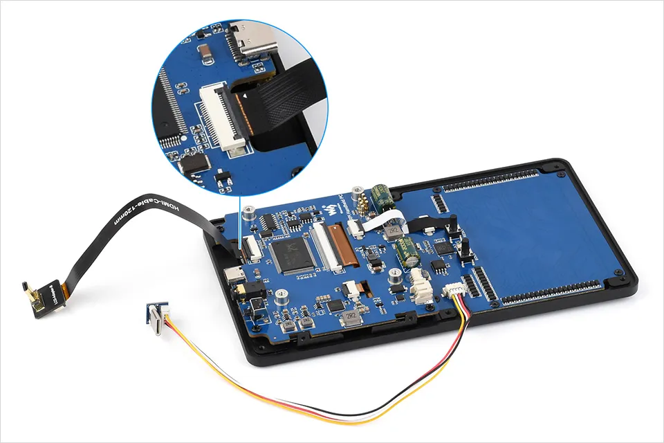
Use accessories ④⑤⑥⑦ to assemble the Micro HDMI cable and USB Type-C cable as shown below.
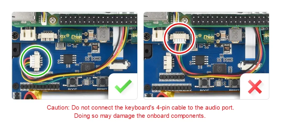
- Before inserting the FPC ribbon cable, make sure the gold contacts are facing the correct direction.
- Do not connect the keyboard 4PIN cable to the audio interface, as this may damage the device.
Step 3: Secure the Raspberry Pi
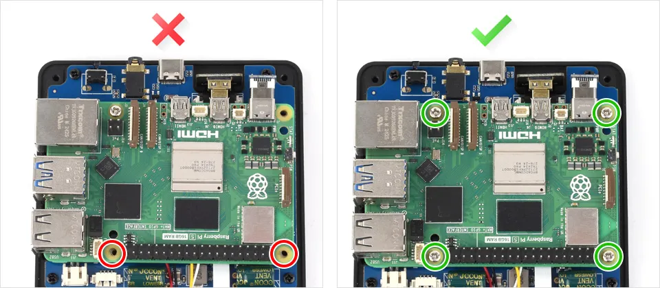
Before securing the Raspberry Pi, ensure the main board is aligned with the brass standoffs to guarantee good pogo-pin contact and avoid misalignment or uneven stress.
Use the 4 PM2.5*4 round-head screws from accessory ⑨ to secure the Raspberry Pi to the PCBA.
Step 4: Connect the Battery (Optional)
If you purchased the version without a battery, skip this step.
Make sure the Raspberry Pi board is correctly installed before connecting the battery to avoid short circuits due to incorrect connection.
Connect the 5000mAh lithium battery (accessory ⑧) to the PH2.0 connector and secure the battery position with double-sided tape.
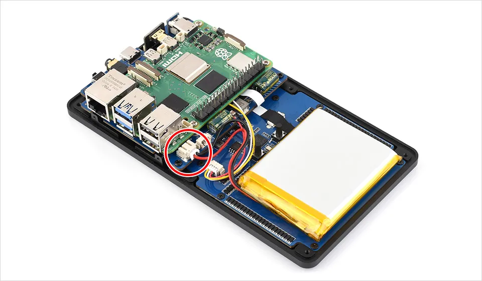
When connecting the battery, the power LED may briefly light up and then turn off. This is normal behavior during power circuit initialization; the device remains powered off.
To power on, press the top power button once.
Step 5: Connect the Speaker and Install the Silicone Button
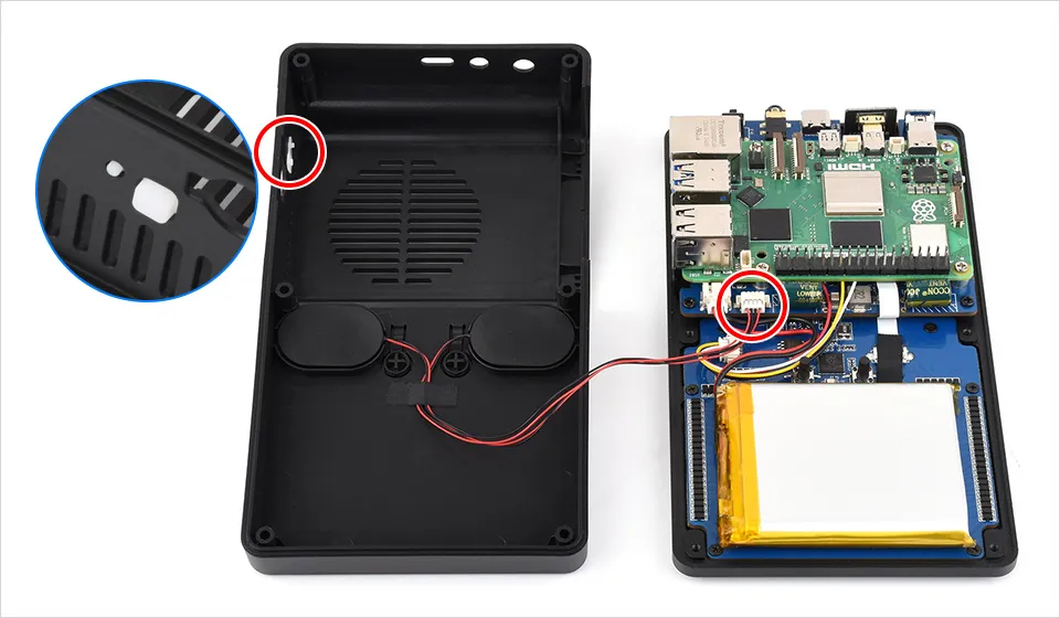
Connect the speaker to the 4PIN PH1.25 audio interface.
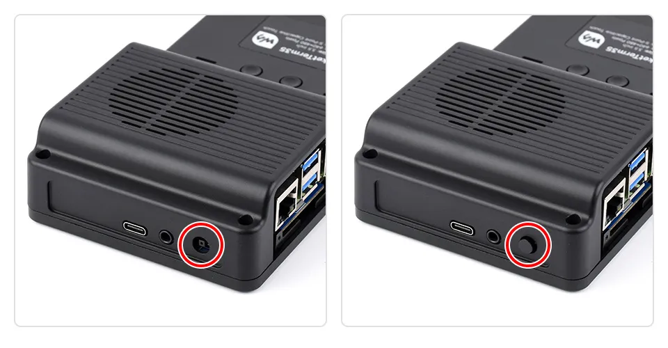
If you are installing a Raspberry Pi 5, attach the Pi 5 side silicone power button (accessory ⑪) to the side wall of the enclosure.
During installation, ensure the silicone button aligns properly with the power button on the Raspberry Pi 5 main board and returns smoothly after pressing. If the button feels too tight or the power-on response is not sensitive enough, you may trim (flatten) the inside of the silicone button slightly and reinstall it.
Step 6: Secure the Back Cover
Before securing the back cover:
- If the black power button cap is already installed, remove it temporarily to avoid damaging it when reinstalling the back cover.
- Make sure cables are not pinched.
- Confirm that the back cover closes naturally.
If the cover does not close easily, do not force it or tighten the screws; re-check the cable routing. Once confirmed, reinstall the 6 PM2.5×12 black screws and the black power button cap.
Step 7: Install the Side Panel
Based on your Raspberry Pi main board, select the corresponding side panel from accessories ②/③ and secure it with KM2×5 black screws.