Working with Raspberry Pi
Working with Raspberry Pi 4B/5
Required Components
- RGB-Matrix-P4-80x40 (included in this product)
- 2 × 8PIN 2.54mm pitch cable (included in this product)
- Raspberry Pi 4B or Raspberry Pi 5 (must be purchased separately)
- 5V external power supply (it is recommended to reserve sufficient current based on the number of panels; must be purchased separately)
Hardware Connection
The Raspberry Pi supports up to 3 ways of connecting to LED matrix panels via shared connections. For ease of wiring, this document uses a unified numbering scheme:
[1]: Panel 1 wiring group[2]: Panel 2 wiring group[3]: Panel 3 wiring group
Note: [1], [2], and [3] represent three independent panel wiring groups, not three completely different interface standards; some control pins are common signals.
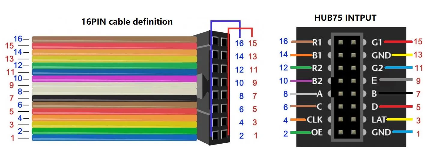
If only one panel is connected, you only need to connect the pins marked [1] and the common pins. The diagram below shows the 16Pin ribbon cable connection:
| Signal (Odd Pin) | Pin | Pin | Signal (Even Pin) |
|---|---|---|---|
| - | 1 | 2 | - |
[3] G1 | 3 | 4 | - |
[3] B1 | 5 | 6 | GND [1][2][3] |
LAT/STB [1][2][3] | 7 | 8 | [3] R1 |
| - | 9 | 10 | E [1][2][3] |
CLK [1][2][3] | 11 | 12 | OE [1][2][3] |
[1] G1 | 13 | 14 | - |
A [1][2][3] | 15 | 16 | B [1][2][3] |
| - | 17 | 18 | C [1][2][3] |
[1] B2 | 19 | 20 | - |
[1] G2 | 21 | 22 | D [1][2][3] |
[1] R1 | 23 | 24 | [1] R2 |
| - | 25 | 26 | [1] B1 |
| - | 27 | 28 | - |
[2] G1 | 29 | 30 | - |
[2] B1 | 31 | 32 | [2] R1 |
[2] G2 | 33 | 34 | - |
[2] R2 | 35 | 36 | [3] G2 |
[3] R2 | 37 | 38 | [2] B2 |
| - | 39 | 40 | [3] B2 |
Hardware Connection
- Install and run the Raspberry Pi OS (Raspbian bullseye)
- After completing the 16PIN wiring according to the table above, connect the 5V power supply to the screen