Software Test
The demonstration introduces the operation methods of the following two software tools. The SSCOM serial port debugging assistant is more convenient to operate, requires no installation, and displays complete commands for easier analysis. The disadvantage is that the data is not intuitive. The Modbus Poll software operates directly on registers, making data display easier to observe. The disadvantage is that commands are not completely displayed, and familiarity with Modbus register operations is required. You can choose either method for testing. It is recommended to use the SSCOM Serial Port Debug Assistant for the first test.
SSCOM Serial Port Debugging Assistant
Modbus RTU Commands
Note: The module is configured with Modbus RTU commands by default.
-
Open the serial port debugging assistant window.
-
Select TCPClient for the port number.
-
Modify the remote IP and port number according to the Vircom settings above.
-
Click the "Connect" button to connect to the TCP server.
-
After successful connection, the Ethernet port green LED will light up.
-
Click to open the Send Multi-Char window. The default displayed commands are Modbus RTU commands. Click the corresponding function to send the corresponding command.
-
If you use the custom input box below to send the commands, you need to set Verify as ModbusCRC16.

Modbus TCP Commands
Note: If you want to use Modbus TCP commands, you need to change the commands.
-
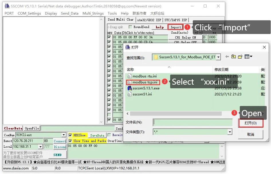
Click on the Import ini button in the Send Multi-Char column.
-
Select the modbus tcp.ini file to import the Modbus TCP command. Note: If an error popup says "A component named HEX0 already exists", you need to close and reopen the software. The software will reload the file and refresh the button.
-
After successful import, the display will look as follows. Click the corresponding function to send the corresponding command. Note: Modbus TCP does not require CRC check. Select None for checksum. Select None for Verify.
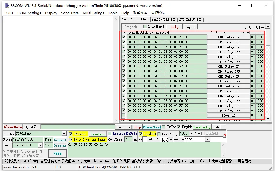
For more detailed Modbus commands, please refer to the Development Protocol.
Modbus Poll Software
Reading Configuration
-
If the serial port software is inconvenient for observing data, you can choose the Modbus Poll software to read data. Download and install the Modbus Poll software.
-
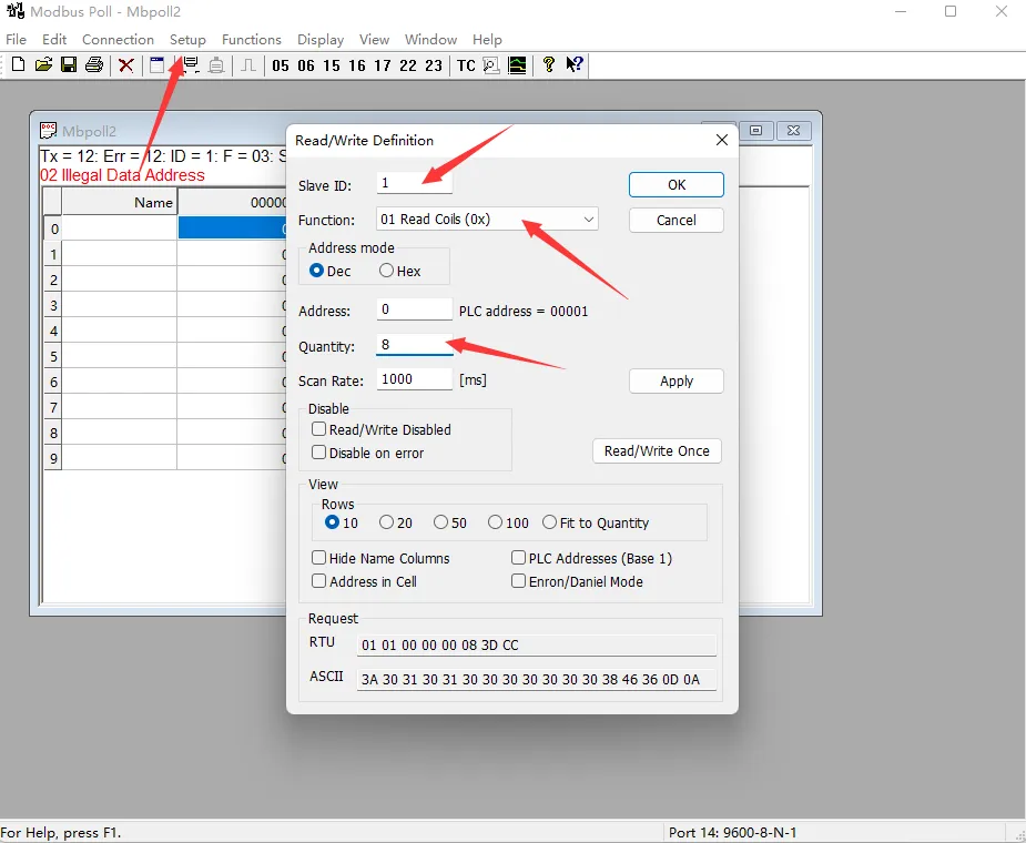
Select Setup -> Read/Write Definition. Select the actual device address for Slave ID, 01 Read Coils for Function, and 8 channels for Quantity. Click OK to confirm.
Protocol Selection and Connection Configuration
- Connection Configuration
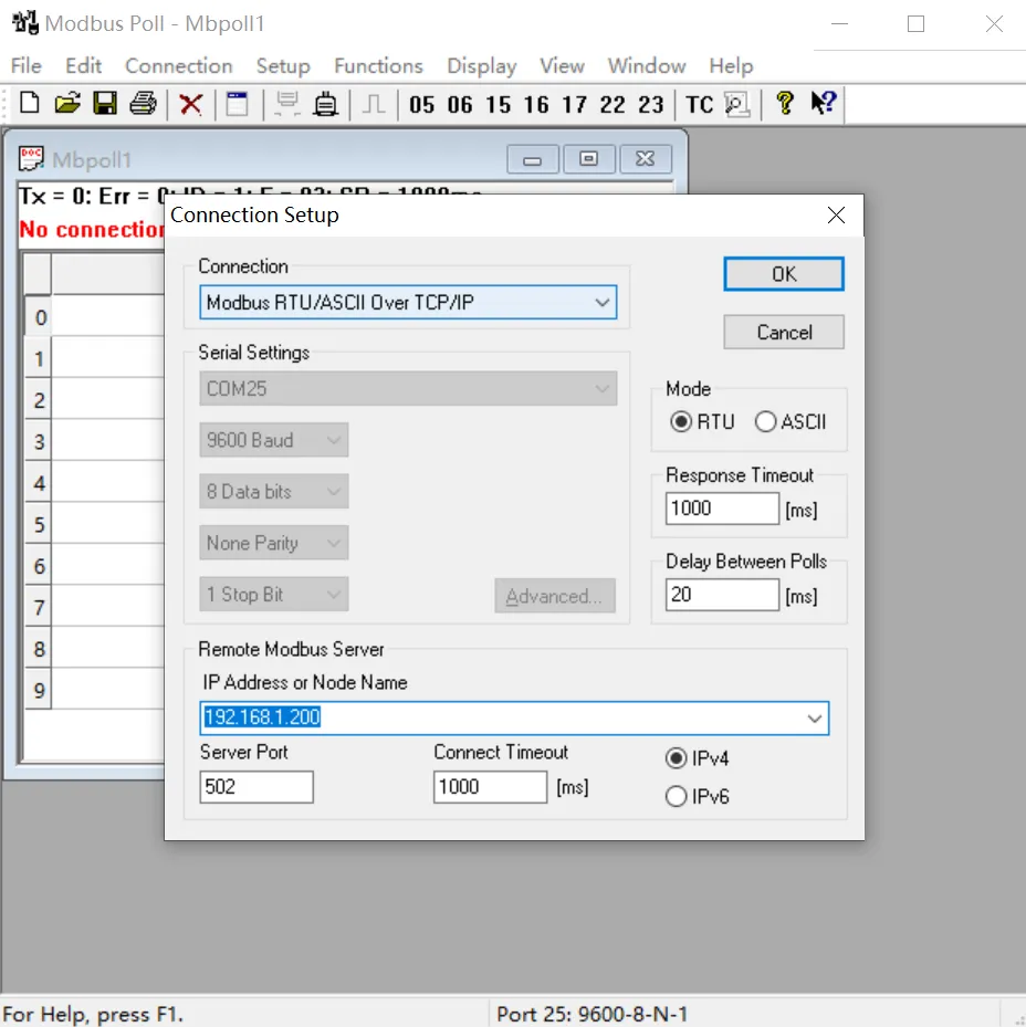
- When using the Modbus RTU protocol: Select Connection -> Connect Setup. Select Modbus RTU/ASCII Over TCP/IP for Connection, select RTU for Mode, and enter the correct IP address and port number. Click OK to connect.
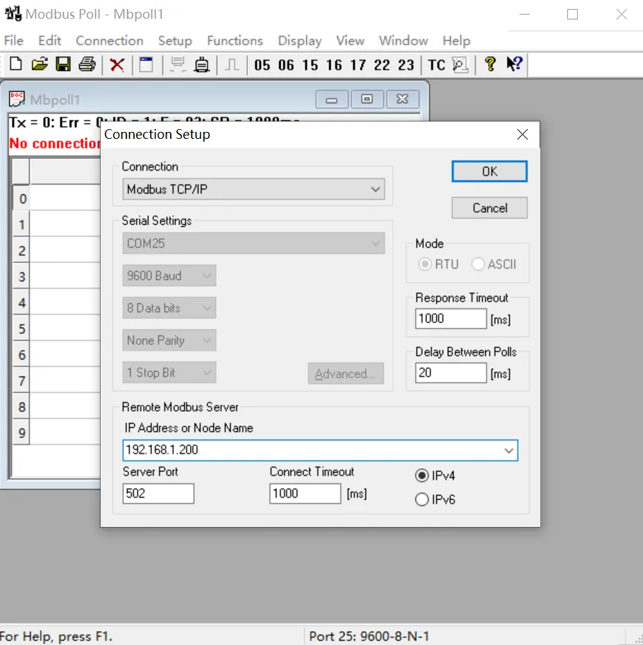
- When using the Modbus TCP protocol: Select Connection -> Connect Setup. Select Modbus TCP/IP for Connection, and enter the correct IP address and port number. Click OK to connect.
- When using the Modbus RTU protocol: Select Connection -> Connect Setup. Select Modbus RTU/ASCII Over TCP/IP for Connection, select RTU for Mode, and enter the correct IP address and port number. Click OK to connect.
Output Control and Input Reading
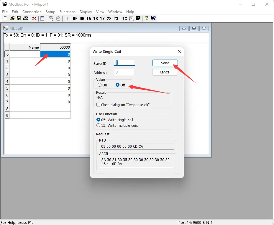
- After successful connection, you can view the current output channel status. Select the corresponding channel, double-click the status value to pop up the sending page. Choose On or Off, then click Send to control the corresponding output channel's on/off status.
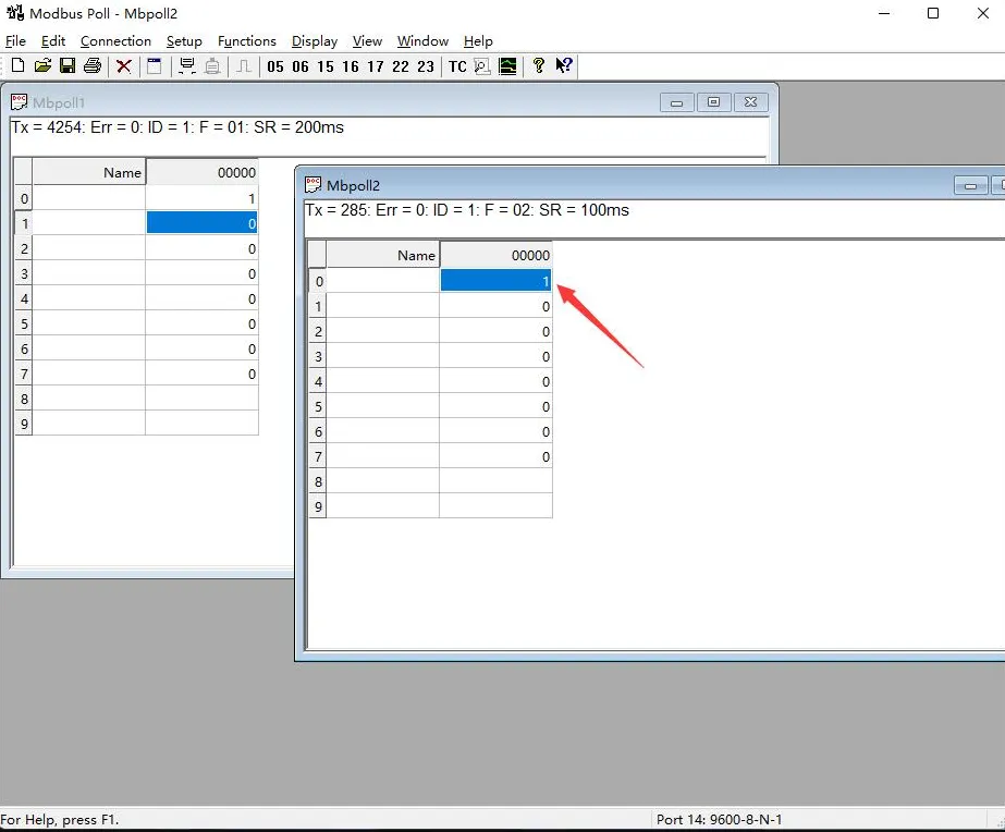
- Choose File -> New to create a new window. Select Setup -> Read/Write Definition, choose the actual device address for Slave ID, select 02 for Function, set Address to 0, set Quantity to 8 channels, and change the Scan Rate to 100ms. Click OK to confirm.
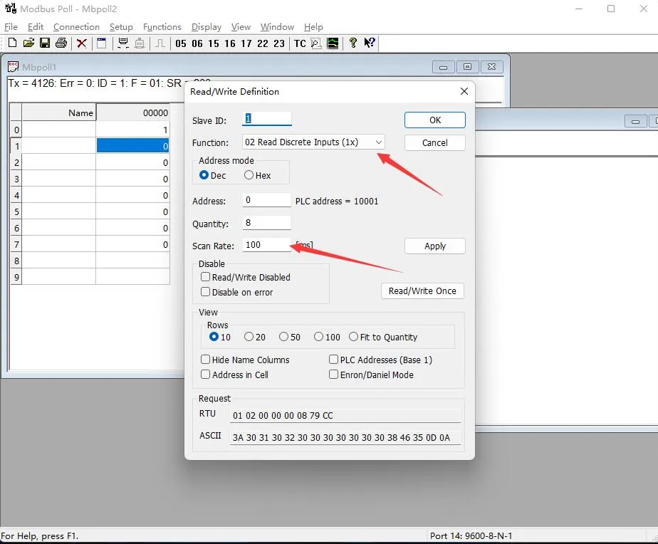
- The newly created window 2 can display the current input status. Changing the input interface level will also change the corresponding value.