FAQ
Q: Where can I download the driver for the device?
A: The device does not require an additional driver. Simply send Modbus commands via the device's RS485 interface to control the output and implement other functions.
Q: Can the slave address be set via DIP switches?
A: There are no DIP switches, but the address can be set using commands.
Q: What should I do if I forget the 485 communication parameters?
A: Please refer to the Modbus series BootLoader instructions to enter boot mode. Then you can select option 3 to read the communication parameters or option 2 to reset the communication parameters.
Q: What should I do if SecureCRT displays garbled text when entering boot mode?
A: Check if the 485 bus is reversed. If it is not reversed, connect a 120 Ω terminating resistor across the A and B lines.
Q: What is the power consumption of the device?
A: With a 12 V power supply, the reference power consumption in standby mode is 0.34 W. Please refer to actual conditions for specific power consumption.
Q: How should I wire the device to measure voltage and current?
A: As shown in the figure, the red line is the positive path, and the black line is the negative path.
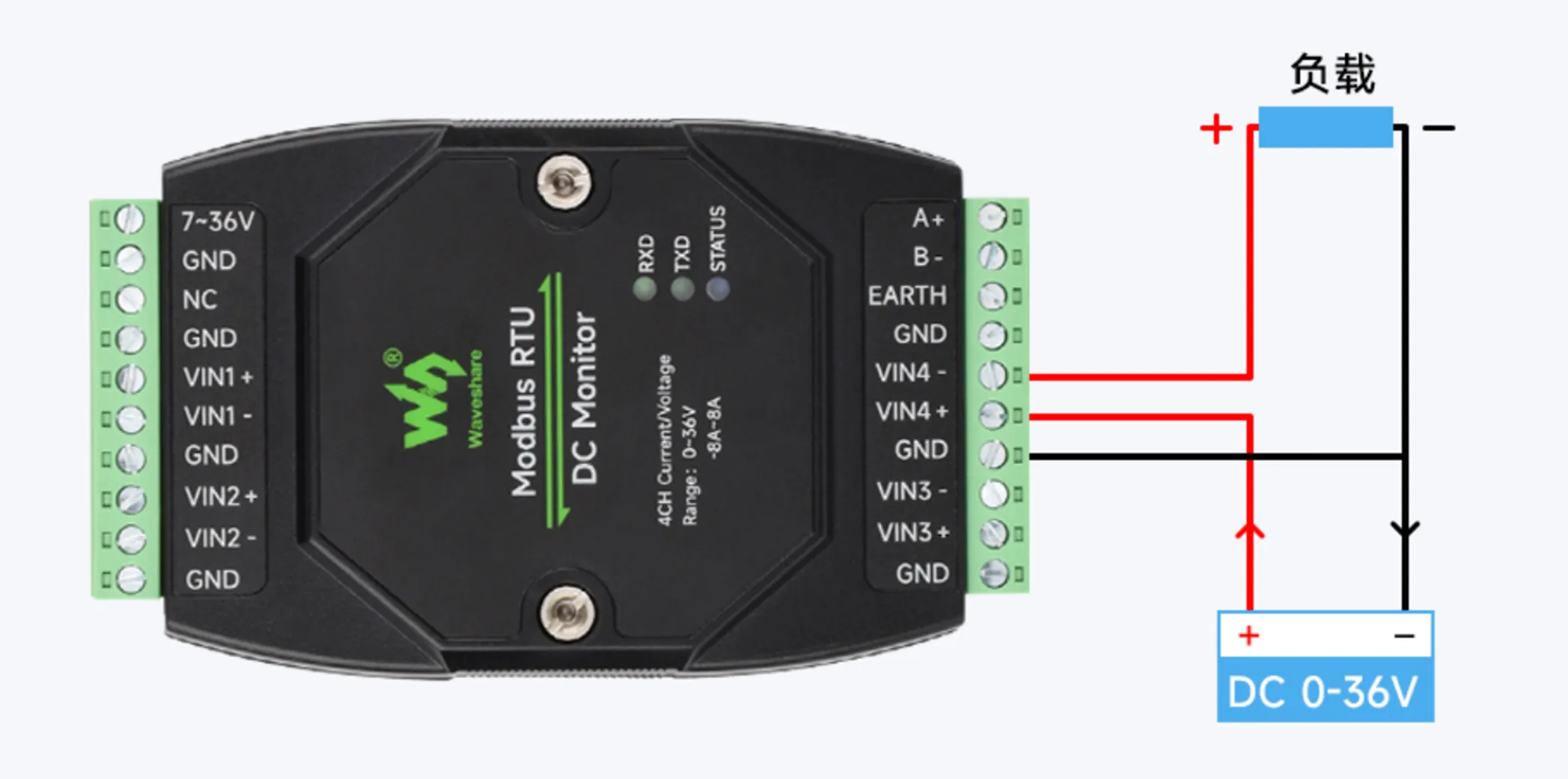
To measure current, the module needs to be connected in series in the positive path of the load. That is, connect the power supply positive to the module's VIN+ first, then connect from VIN- to the load positive. The load negative is connected directly back to the power supply negative, forming a complete power supply loop.
A current sensing circuit is built in between VIN+ and VIN-. After the load current flows through this path, the module can measure the current. The VIN- terminal still outputs the power supply positive, so it should be connected to the load positive.
At the same time, to measure voltage accurately, the module's GND needs to be connected to the power supply negative (DC-), so that the module and the power supply under test share a common ground, providing a reference potential for voltage measurement.
In simple terms:
Positive path: Power supply positive → Module VIN+ / VIN- → Load positive
Negative path: Load negative → Power supply negative
Reference ground: Module GND → Power supply negative
Among these, VIN+ / VIN- are used for series current measurement, and GND is used to provide the reference ground for voltage measurement.
If VIN+ and VIN- are connected directly to the power supply positive and negative respectively, it is equivalent to connecting the internal current sampling resistor directly across the power supply, which may generate excessive current and damage the module.