Software Test
SSCOM Serial Debug Assistant
Basic Query Commands
-
Download the SSCOM Serial Debug Assistant and open it on your computer. Open the corresponding port number, set the baud rate to 9600, select SendHex and Receive, and choose ModbusCRC16 check for the checksum.
Send the following command. Under normal conditions, channel 1 will output a pulse with a frequency of 1 kHz and a duty cycle of 50%.
01 10 00 00 00 03 06 00 01 86 A0 13 88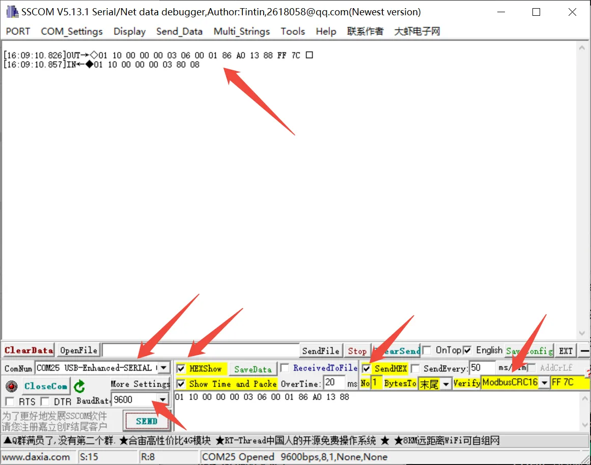
Other Commands
-
If you need to send other commands, select SendHEX, choose ModbusCRC16 check for the checksum, enter the first six bytes of the command, and click SEND, it will automatically add the CRC check code.
For example, sending the following command sets channel 1 duty cycle to 20%.
01 06 00 02 07 D0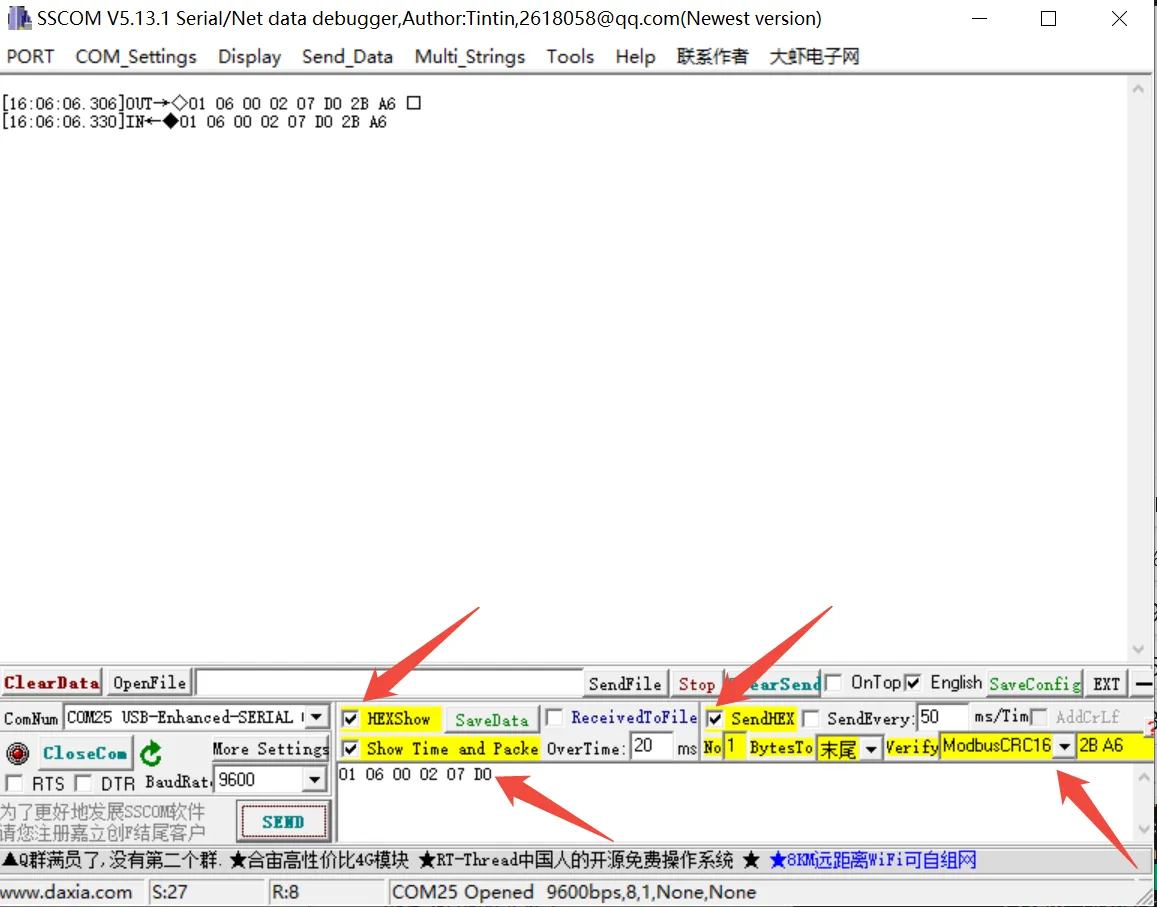
For more detailed control commands, please refer to the development protocol.
Modbus Poll Software
-
The serial software is not convenient for data observation. You can use the Modbus Poll Software to read data. Download and install the Modbus Poll software.
-
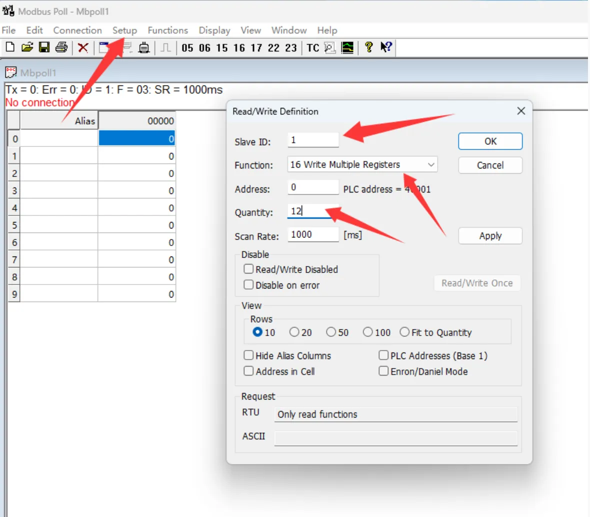
Open the software, select Setup -> Read/Write Definition. Set Slave ID to the actual device address, select Function 16, change Quantity to 12 channels. Click OK to confirm.
-
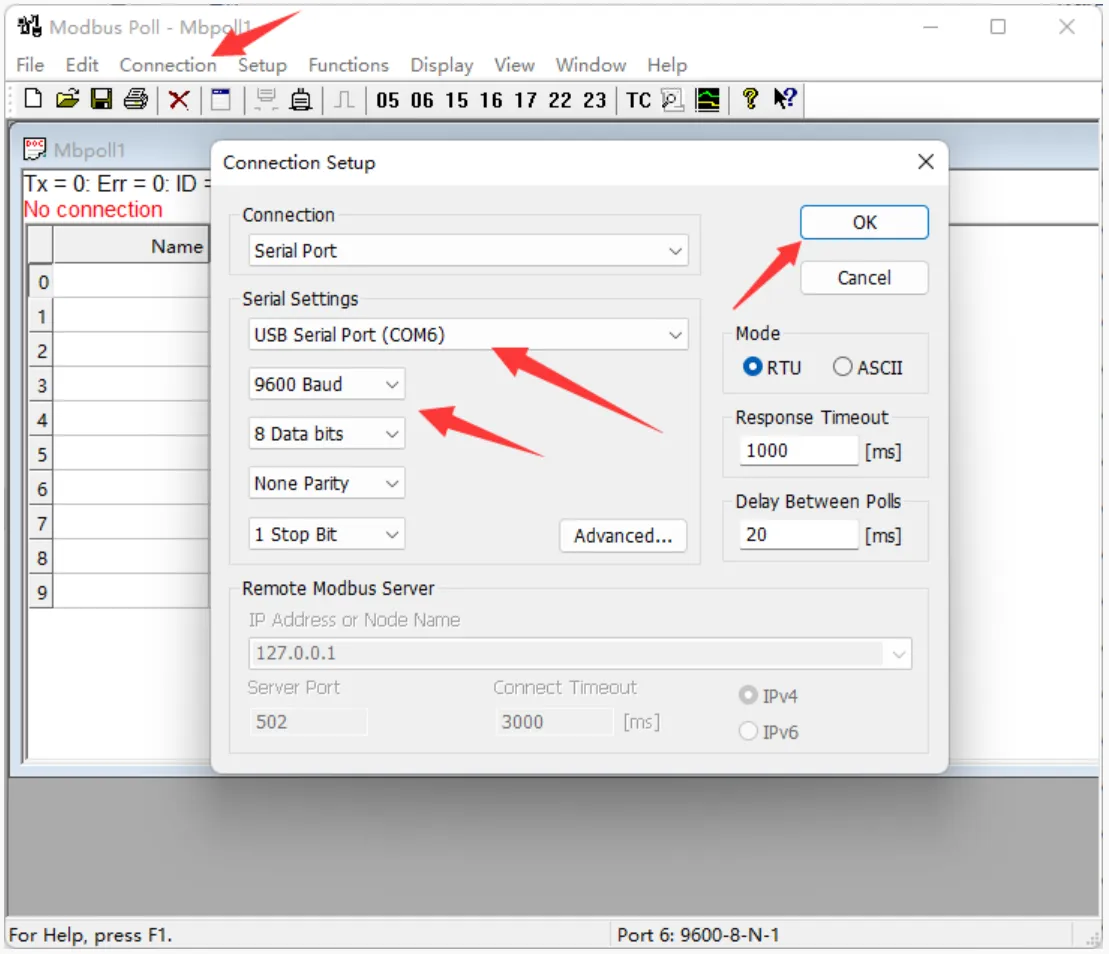
Select Connection -> Connect..., choose the corresponding serial port, set baud rate to 9600, 8 data bits, no parity, 1 stop bit. Click OK to connect.
-
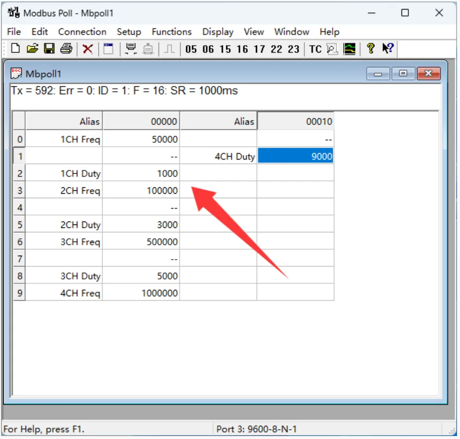
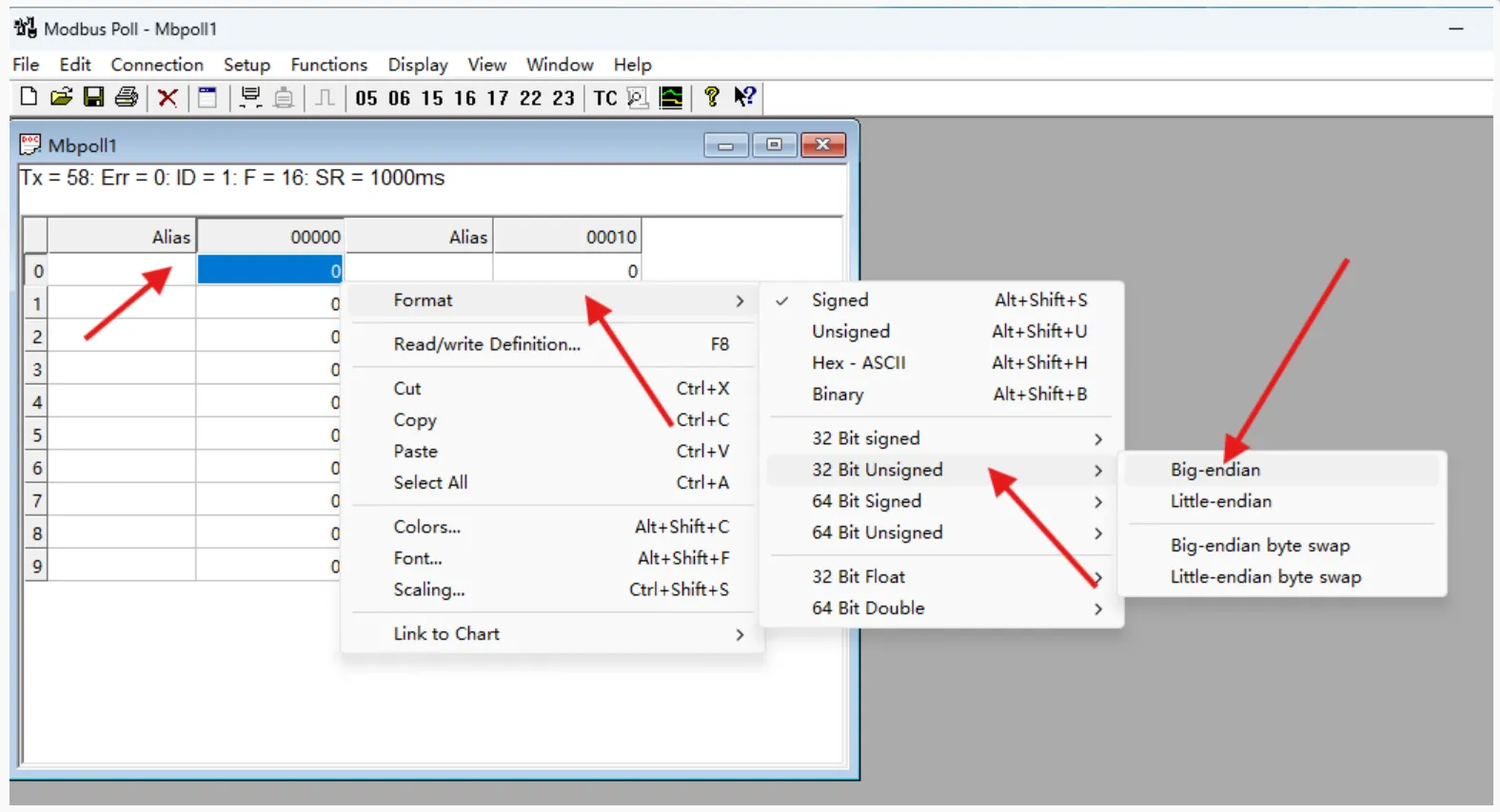
After successful connection, set the frequency format. Select registers 0, 3, 6, 9 and set their format to Unsigned 32-bit Big-endian. You can also add register notes in the Alias column.
-
Enter the channel frequency and duty cycle in the registers; the corresponding pulse will be output. Frequency range: 100
100000000, i.e., 1 Hz200 kHz. Duty cycle range: 010000, i.e., 0100%.The figure below shows the settings: Channel 1: 500 Hz, 10%; Channel 2: 1 kHz, 30%; Channel 3: 5 kHz, 50%; Channel 4: 10 kHz, 90%.