Preparation Before Use
Before you start, complete the following steps in order: Check the contents against the unboxing list → Perform the mechanical pre-inspection → Understand the appearance and interface description → [Connect power and turn on the device].
1. Unboxing List
Please check the following list to confirm that all accessories are complete and undamaged. If anything is missing or damaged, do not power on the device and contact technical support immediately.
| No. | Name | Image | Description | Description |
|---|---|---|---|---|
| 1 | RoArm-M2-GA Robotic Arm Main Unit | 1 | 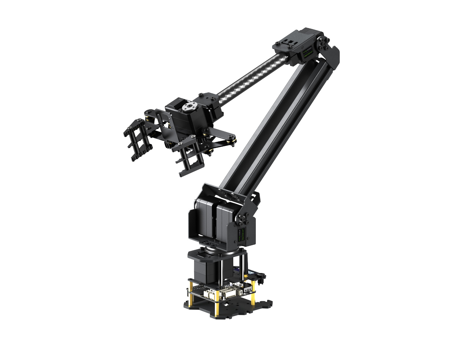 | Robotic arm main unit |
| 2 | 12V 5A Power Adapter | 1 | 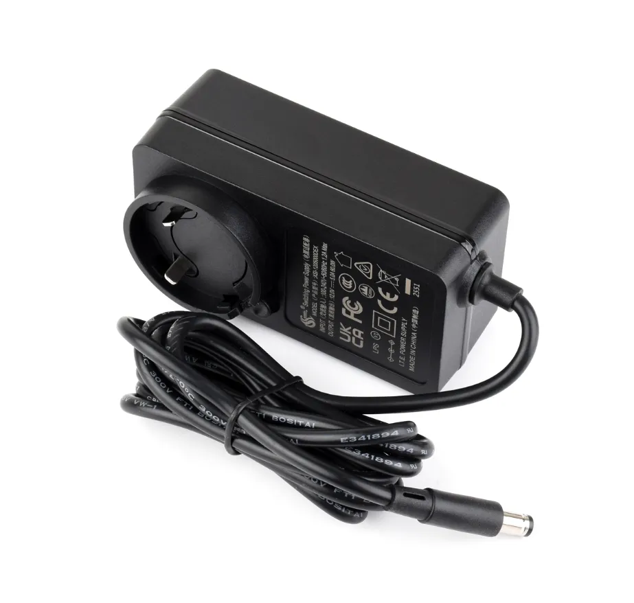 | Provides 12V 5A operating power. Must use the official adapter |
| 3 | Detachable Power Plug Adapter | 1 | 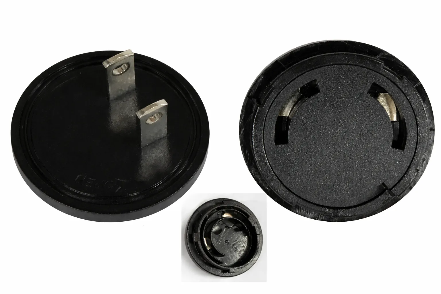 | Adapts to wall socket standards in different countries/regions. Interchangeable plug pins |
| 4 | Desktop Mounting Clip | 1 | 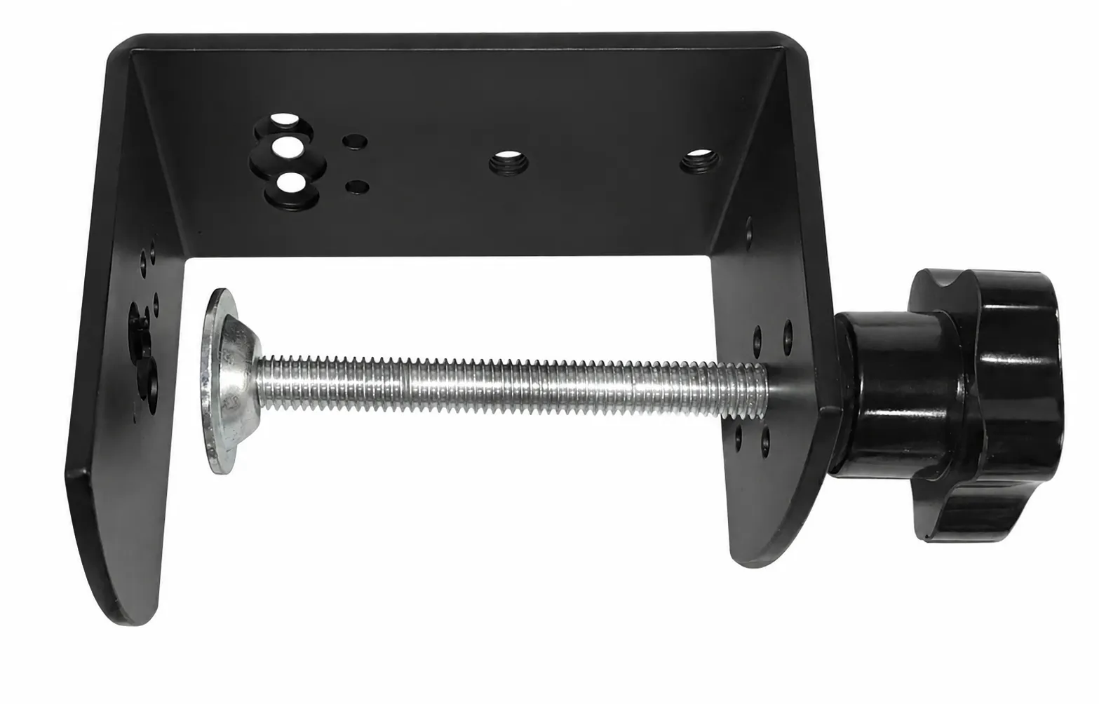 | Can be assembled with the arm to clamp it securely to the edge of a desk, preventing movement or tipping during operation and improving safety |
| 5 | Jetson Nano Adapter (C) | 1 |  | Onboard level-shifting IC for UART serial communication between the robotic arm and a host computer (Raspberry Pi / Jetson Orin Nano / RDK, etc.). Improves communication stability on host computers with weak UART drive capability |
| 6 | USB Cable (Type A Male to Type C Male) | 1 |  | For USB serial communication between the robotic arm and a host computer (PC/Raspberry Pi, etc.) |
| 7 | Dual-Row Dupont Wire (2×5PIN, 2.54mm pitch, 9cm, same direction) | 1 |  | For extended UART serial wired communication between the robotic arm and a host computer |
| 8 | Rail Mounting Plate | 1 |  | Extension board with T-slot rails; can be mounted on the upper arm for attaching external devices |
| 9 | Lightweight Base Plate | 1 |  | Lightweight fixing plate for weight-sensitive mobile platform installations |
| 10 | Camera Mount | 1 |  | Used to attach a camera to the end effector or body of the arm for vision recognition applications (note: the onboard driver board has no camera interface; vision applications require an external host computer) |
| 11 | 5264 Servo Cable (3PIN, 900mm, opposite direction) | 1 | 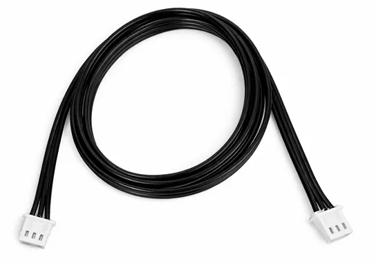 | Spare servo bus cable for end-effector expansion or servo replacement |
| 12 | Small Cross Sleeve | 1 |  | Can be used to tighten hexagonal standoffs |
| 13 | Black Rubber Bands (30mm diameter, 5mm width) | 8 |  | Use the elastic force of the rubber bands to compensate for gravity and increase the arm's payload |
| 14 | Dual-Size Hex Screwdriver | 1 |  | For disassembling/assembling screws on the arm body. Supports two hex sizes for different parts |
| 15 | RoArm-M2 Screw Kit:
| 1 | 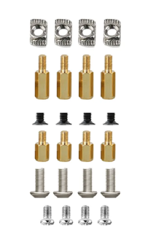 | Spare screws for mounting the base, attaching expansion brackets, and securing various peripherals |
2. Mechanical Pre-inspection
Before connecting power to the robotic arm, inspect the device in the following order:
-
Shipping damage check:
- Check the enclosure and each joint component for deformation, cracks, or damage caused during shipping.
✅ Pass criteria: Intact appearance, no obvious deformation or damage.
- Check the enclosure and each joint component for deformation, cracks, or damage caused during shipping.
-
Screw tightening check:
- Check that all screws on the arm are tight, especially at joint connections.
✅ Pass criteria: No loose screws, joints securely fastened.
- Check that all screws on the arm are tight, especially at joint connections.
-
Cable check:
- Verify that cable connectors between joints are firmly attached.
- Check that all exposed cables are intact, with no damage or kinking from packaging.
✅ Pass criteria: Secure cable connections between joints, all cable sheaths intact with no breaks, exposed wires, or abnormal creases.
-
Joint movement check:
- Remove the arm from packaging and manually rotate each joint to verify smooth movement.
✅ Pass criteria: Each joint moves freely without sticking or grinding.
- Remove the arm from packaging and manually rotate each joint to verify smooth movement.
If any of the above checks fail, do not power on the device. Contact technical support before continuing.
3. Appearance and Interface Description
Below are the device's external appearance and interface layout.
3.1 Base Interface and Functions
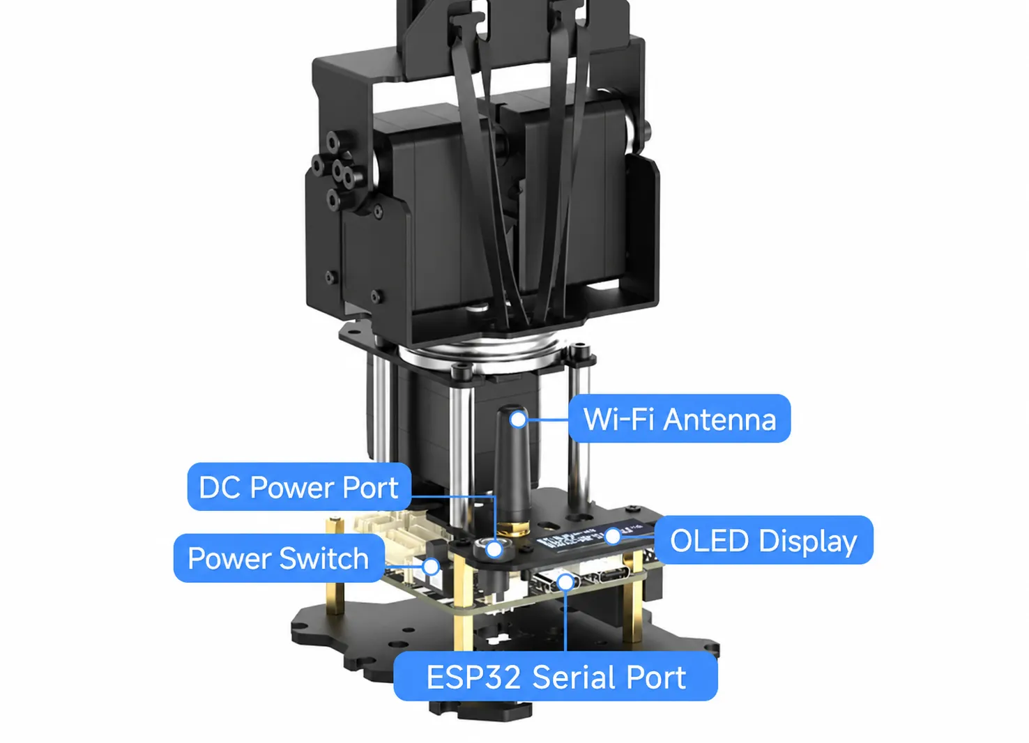 Labeled base interfaces of the robotic arm
| Name | Description |
|---|---|
| Wi-Fi Antenna | Connects to the ESP32 module inside the base for Wi-Fi wireless communication |
| OLED Display | Displays real-time status: current network mode (AP/STA), MAC address, voltage, etc. See OLED Status Description |
| DC Power Jack | DC power input. Use the official Waveshare 12V 5A power adapter |
| Power Switch | Controls main power. Toggle to ON for power-on, OFF for power-off |
| ESP32 Serial Communication Interface | Used for firmware flashing and wired serial communication with a host computer (Raspberry Pi / Jetson, etc.) |
4. Power-on and Connection
Before power-on, confirm:
- The base is securely fixed and there are no obstructions around the robotic arm.
- For first-time use, do not mount heavy objects or perform complex tasks – ensure stable operation.
Step 1: Connect Power
With the power switch in the OFF position, plug the official power adapter into the DC jack on the base, then plug the adapter into a outlet. Finally, toggle the power switch to ON.
After power-on, the driver board's LED lights red, but the LED being on does not necessarily mean the arm is powered by the adapter – the LED also lights when only the USB cable is connected.
To check proper power-supply, look at the voltage value on the fourth line of the OLED display:
- ~12 V displayed → The arm is correctly powered by the adapter ✅
- ~0 V displayed → The adapter is not connected or the power switch is off ❌
Step 2: Device Initialization
After power-on, the device initializes automatically. During initialization, each joint moves to its initial position. Ensure no obstructions are within the arm's range of motion.
Users can change the initial position following the [Custom Initial Position tutorial]. After modification, the arm will move to the user-set initial position (not the neutral pose) each time it powers on.
Step 3: Check OLED Display Status
After initialization, the base OLED screen shows the following:
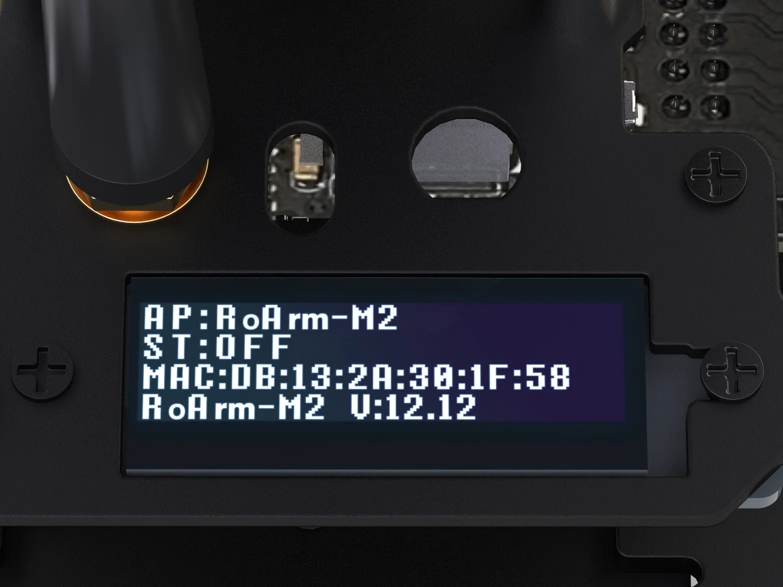
The meaning of each line shown above is as follows:
| Line | Field | Meaning |
|---|---|---|
| 1 | AP:RoArm-M2-GA | Current Wi-Fi mode is AP (Access Point); the hotspot name is RoArm-M2-GA |
| 2 | ST:OFF | STA mode is off. If connected to a router, this line shows the IP address assigned by the router |
| 3 | (e.g.) MAC:DB:13:2A:30:1F:58 | Unique MAC address of the device, used for identification in ESP-NOW multi-arm communication |
| 4 | RoArm-M2-GA V:12.12 | Indicates the model (RoArm-M2-GA series) and the real-time voltage; can be used to check power supply status |
Step 4: Connect to WiFi
Find and connect to the following hotspot on your phone or computer:
-
Hotspot name:
RoArm-M2-GA -
Password:
12345678
Step 5: Open the Web Control Interface
We recommend using Google Chrome for the best compatibility and display. If you don't have Chrome, you can click here to download it.
If the download link above does not work, go to the Resources and Documents page, download the offline Chrome installer, and install it locally.
After connecting to Wi-Fi, open a browser on your phone or computer, enter 192.168.4.1 in the address bar, and press Enter. Seeing the interface below means the connection is successful.
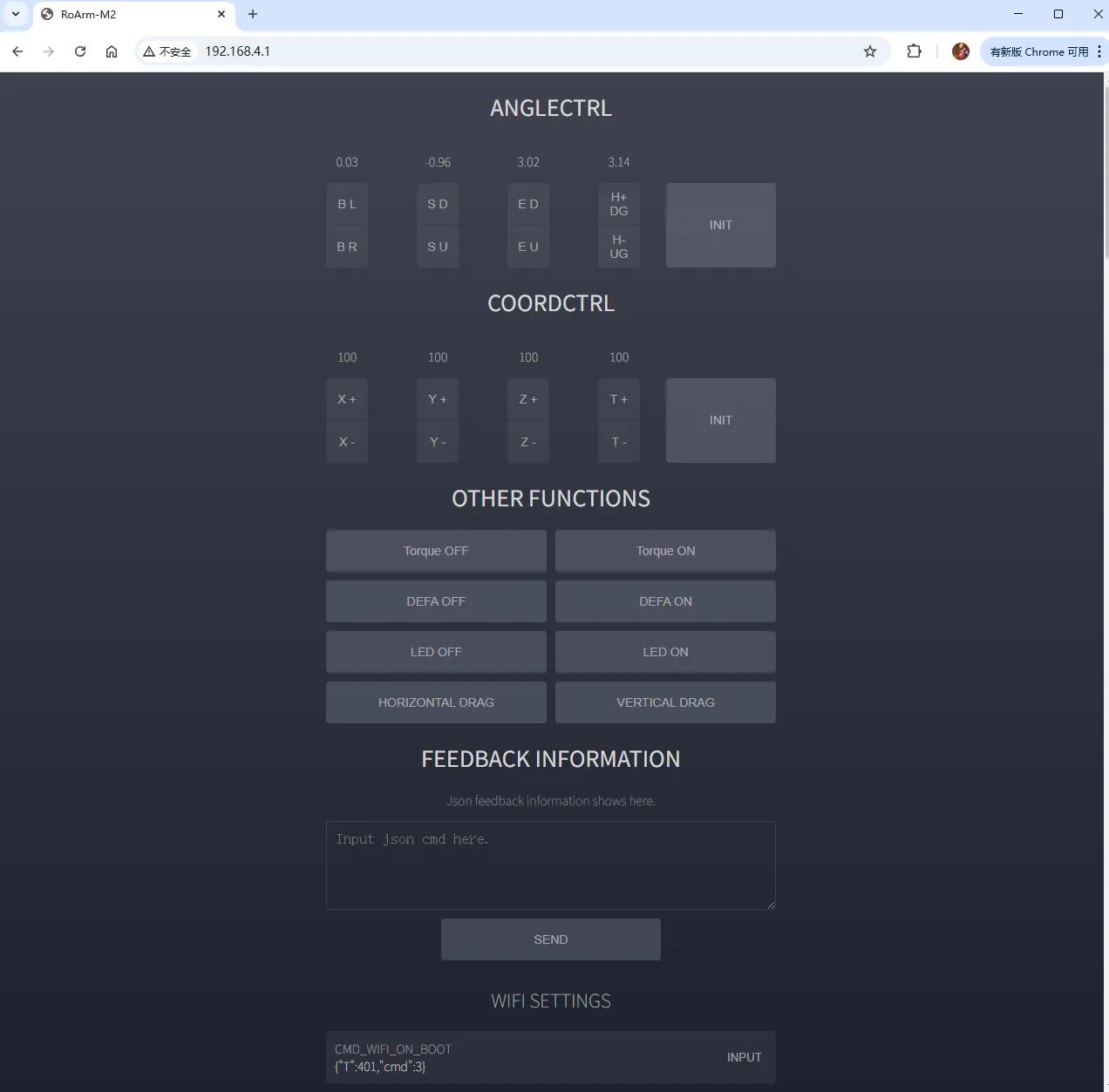 Web Control Interface
The Web control interface is accessible from a mobile browser, but due to screen size, the touch targets are small. Some buttons require a long-press to trigger continuous motion, and sensitivity and accuracy are reduced compared to a computer. We recommend controlling the robotic arm via a desktop browser for the optimal operating experience.
After completing the above steps, go to the Getting Started interface to make the robotic arm move.