Web Control Interface Usage
This section introduces in detail how to use each functional module in the Web control interface.
Before starting, please complete the steps in Preparation → Power-on and Connection and ensure that the Web control interface is open.
The Web control interface is divided into the following functional modules from top to bottom:
| Module | Description | Function Overview |
|---|---|---|
| ANGLECTRL |  | Control the rotation angle of each joint via buttons |
| COORDCTRL |  | Control the spatial coordinate position of the end-effector via buttons; it is recommended to read the Coordinate System Description first to understand the axis directions |
| OTHER FUNCTIONS |  | Other function buttons, such as torque lock, LED switch, etc., see below for details |
| FEEDBACK INFORMATION |  | Manually send JSON commands and display the corresponding feedback information from the robotic arm |
1. ANGLECTRL
The ANGLECTRL module is used to directly control the rotation angle of each joint of the robotic arm, which is the most basic control method.
The joint angles in the interface are displayed in radians, not in the everyday unit "degrees". The conversion relationship is as follows:
| Radian Value | Corresponding Angle |
|---|---|
| 0 | 0° |
| 1.57 | 90° |
| 3.14 | 180° |
| -1.57 | -90° |
| -3.14 | -180° |
When using it for the first time, simply refer to it; you can judge the joint rotation by observing the change direction of the numbers on the buttons.
1.1 Joint Button Description
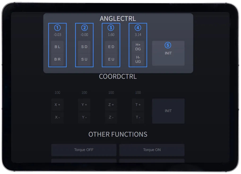 Angle Control Button Annotation
The number displayed above each column of buttons is the current angle (in radians) of that joint.
- The joint moves only while the button is held down; it stops immediately when the button is released.
- The number above the button refreshes only after the button is released, updating to the current position;
- When a joint has reached its limit, further clicking the same direction button will have no response. You need to click the opposite direction button to move the joint away from the limit before continuing control.
Button operations are described below:
① Base Joint —— B L / B R
The base joint is the rotating joint of the robotic arm base, controlling the entire arm's left and right rotation.
- Rotation range: 360° (-3.14 to 3.14 radians)
- After power-on, the base joint automatically moves to the neutral position, where the number is 0.
| Button | Operation Description |
|---|---|
B L | Press and hold; the base joint rotates left, and the angle value increases |
B R | Press and hold; the base joint rotates right, and the angle value decreases |
Starting from the neutral position:
- Press and hold
B Lto the limit; the number increases from 0 to 3.14 (rotate left 180°);- Press and hold
B Rto the limit; the number decreases from 0 to -3.14 (rotate right 180°).
② Shoulder Joint —— S D / S U
The shoulder joint controls the forward and backward pitch of the robotic arm's upper arm.
- Rotation range: 180° (-1.57 to 1.57 radians)
- After power-on, the base joint automatically moves to the neutral position, where the number is 0.
| Button | Operation Description |
|---|---|
S D | Press and hold; the shoulder joint rotates forward, and the angle value increases |
S U | Continuously clicking rotates the shoulder joint backward, decreasing the angle value. |
Starting from the neutral position:
- Continuously clicking
S Dto the limit increases the value from 0 to 1.57 (rotating forward 90°);- Continuously clicking
S Uto the limit decreases the value from 0 to -1.57 (rotating backward 90°).
③ Elbow Joint —— E D / E U
The elbow joint controls the forward and backward bending of the robotic arm's forearm.
- Rotation range: 180° (0 to 3.14 radians)
- After power-on, the base joint automatically moves to the neutral position, where the number is 1.57 (i.e., the forearm is at 90° relative to the upper arm).
| Button | Operation Description |
|---|---|
E D | Continuously clicking rotates the elbow joint forward, increasing the angle value. |
E U | Continuously clicking rotates the elbow joint backward, decreasing the angle value. |
Starting from the neutral position:
- Continuously clicking
E Dto the limit increases the value from 1.57 to 3.14 (rotating forward 90°);- Continuously clicking
E Uto the limit decreases the value from 1.57 to 0 (rotating backward 90°).
④ End Joint —— H+ DG / H- UG
- Rotation range: 90° (0 to 1.57 radians)
- After power-on, the gripper automatically moves to the neutral position. It is open by default, and the digital display will show 1.57 at this time.
| Button | Operation Description |
|---|---|
H+ DG | Continuously clicking opens the gripper, increasing the angle value. |
H- UG | Continuously clicking tightens the gripper, decreasing the angle value. |
Starting from the neutral position:
- The gripper is open by default upon power-on (1.57);
- Continuously clicking
H- UGto the limit decreases the value from 1.57 to 0.
⑤ Reset All Joints —— INIT
After clicking INIT, all joints will automatically move back to the neutral position (i.e., the factory default initial position).
INIT returns to the neutral position, not the user-defined initial position. If you have modified the power-on initial position via the [Custom Initial Position Tutorial], clicking INIT will still return the arm to the neutral position, not the position you set.
1.2 Summary of Joint Rotation Ranges
| Joint | Middle Position (rad) | Rotation Range | Min (rad) | Max (rad) |
|---|---|---|---|---|
| Base Joint | 0 | 360° | -3.14 | 3.14 |
| Shoulder Joint | 0 | 180° | -1.57 | 1.57 |
| Elbow Joint | 1.57 | 180° | 0 | 3.14 |
| End Joint (Gripper Type) | 1.57 | 90° | 0 | 1.57 |
- Software limit: Each joint has a software limit (as above). When the robotic arm is powered on (except when the torque lock is off), do not forcibly twist the joint, otherwise the servo gears may be damaged;
- Hardware limit: Each joint is also limited by its structure. When the torque lock is off or the arm is not powered on, do not forcibly twist the joint beyond the ranges in the table above, otherwise the servo cables may be worn.
2. COORDCTRL
ANGLECTRL gives commands to "each joint individually", whereas the COORDCTRL module tells the arm directly "where the end-effector should go" — the arm automatically calculates how each joint needs to cooperate. This method is suitable for scenarios requiring precise control of the end-effector position, such as picking up objects at fixed positions.
When you enter a target coordinate in COORDCTRL, the arm internally runs an "inverse kinematics" algorithm: it calculates the angles each joint must rotate to reach the target position, then drives the joints accordingly. The user does not need to manually calculate joint angles; just enter the target coordinates to achieve end-effector position control.
2.1 Coordinate System Description
Before using coordinate control, you must understand the coordinate system definition used by this robotic arm in order to determine the direction in which the end-effector will move when pressing the X +/X -, Y +/Y -, Z +/Z - buttons.
The robotic arm coordinate system is defined based on the right-hand rule, as follows:
| Axis | Description |
|---|---|
| X Axis | Points directly forward (horizontal) from the robotic arm |
| Y Axis | Points to the left (horizontal) of the robotic arm |
| Z Axis | Points vertically upward |
| Coordinate Origin | The reference origin of the robotic arm's motion coordinate system; the reference position for coordinate control |
| End Point | The reference point at the tip of the end-effector; the actual control object for coordinate control |
The right-hand rule is a quick way to determine the direction of a three-dimensional coordinate system without needing a drawing — you can verify with your right hand:
- Extend your right hand naturally;
- Point your index finger towards the positive X-axis direction (directly forward from the arm);
- Point your thumb towards the positive Z-axis direction (vertically upward);
- The direction your middle finger naturally bends points to the positive Y-axis direction (to the left of the arm).
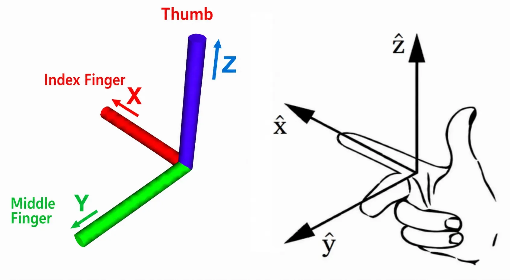 Right Hand Rule Diagram
Verification method: Compare with the physical arm, form the right-hand pose shown in the image, confirm that the three fingers align with the arm's forward, left, and upward directions, then you can correctly determine the positive and negative directions of each axis.
When determining axis directions, refer to the coordinate annotation diagram above and compare with the physical arm. Confirm the X/Y/Z directions before operating to avoid collisions caused by incorrect direction operations.
2.2 End Point Description
The end point is the reference point at the tip of the end-effector, and it is the actual object of coordinate control.
In the coordinate control interface, the displayed X / Y / Z values (unit: mm) are the position coordinates of the end point in space relative to the coordinate origin. When you click the direction buttons, the arm drives all joints to move cooperatively, moving the end point one step in the specified direction, rather than rotating a single joint individually.
Example: Click
Z +, the end point moves vertically upward a certain distance, while in fact both the shoulder and elbow joints adjust their angles to cooperate with this movement.
The exact position of the end point depends on the installed end-effector type:
- Gripper type: the end point is located at the middle of the fixed fingertip of the gripper;
- Wrist type: the end point is located at the center of the wrist tip.
Therefore, after changing the end-effector, the actual spatial position of the end point changes accordingly. When in use, always refer to the actual installed type.
2.3 Button Operation Description
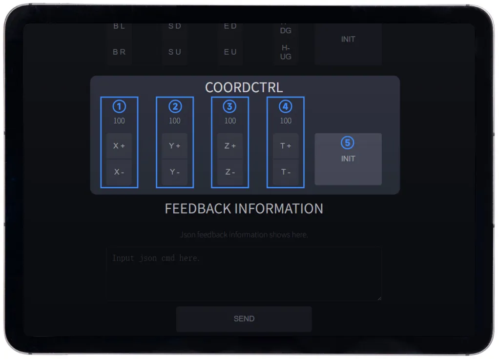 Coordinate Control Button Annotation
The number displayed above the X +/X -, Y +/Y -, Z +/Z - buttons is the end point position coordinate (unit: mm) of the robotic arm, defaulting to 100 mm.
T +/T - controls the rotation angle (in radians) of the end joint (gripper/wrist), corresponding to the end joint description in ANGLECTRL.
The operation descriptions for each button are as follows:
| Button | Operation Description |
|---|---|
X + | End point moves forward (positive X direction) |
X - | End point moves backward (negative X direction) |
Y + | End point moves left (positive Y direction) |
Y - | End point moves right (negative Y direction) |
Z + | End point moves upward (positive Z direction) |
Z - | End point moves downward (negative Z direction) |
T + | End joint forward rotation opens the gripper. |
T - | End joint reverse rotation tightens the gripper. |
INIT | Resets all joints to the neutral position. |
INIT returns to the neutral position, not the user-defined initial position. If you have modified the power-on initial position via the [Custom Initial Position Tutorial], clicking INIT will still return the arm to the neutral position, not the position you set.
3. OTHER FUNCTIONS
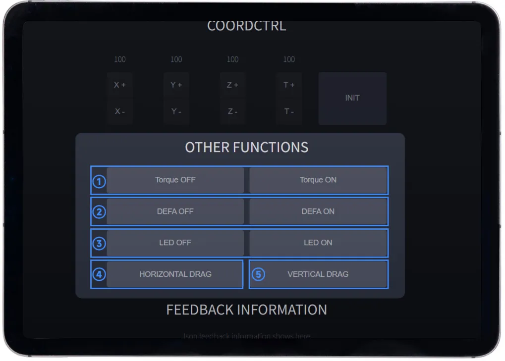 Other Functions Button Annotation
The button operations are described below.
3.1 Torque OFF / ON
This function determines whether the torque lock of the joint servos is "locked":
| Button | Meaning | Applicable Scenarios |
|---|---|---|
Torque OFF | Torque lock off, servo torque released; joints can be freely moved by hand | Used during manual positioning or teaching recording |
Torque ON (Default) | Torque lock on, servos locked; joints hold position and cannot be moved by external force | Used during normal control |
-
When the torque lock is on, do not manually force the joints, as this may damage the servo gears;
-
After clicking
Torque OFF, the arm will first automatically move to the horizontal state, and then you can freely adjust the joint angles by hand; -
After torque is off, the arm relies on its own structure for support. Do not apply external force exceeding the rated load in this state to avoid damaging the joints;
-
During torque off, if any joint receives a rotation command (e.g., clicking a button in ANGLECTRL or COORDCTRL), the torque lock will automatically re-engage.
3.2 DEFA OFF / ON
DEFA (Dynamic External Force Adaptive) is a flexible interaction function. The DEFA OFF / ON buttons quickly toggle this function.
When this function is enabled, the arm sets a maximum output torque limit for each joint:
- When the external force you apply exceeds this limit, the corresponding joint rotates in the direction of the external force;
- When the external force drops below the limit, the joint automatically returns to its position before rotation.
| Button | State | Meaning |
|---|---|---|
DEFA OFF | Dynamic External Force Adaptive off (default) | All joints restore full torque output; external force cannot move joints |
DEFA ON | Dynamic External Force Adaptive on | Joint torque is limited; external force above the threshold can move the joint; the joint automatically rebounds when released |
When DEFA is turned on, the default maximum output torque limits for each joint are as follows (unit: 0.1%):
| Joint | Default Torque Limit |
|---|---|
| Base Joint | 60 |
| Shoulder Joint | 110 |
| Elbow Joint | 50 |
| End Joint | 50 |
The higher the torque limit, the greater the external force required, and the faster the joint rebounds; conversely, the lower the torque limit, the smaller the external force needed to move the joint, but the rebound speed becomes slower.
The default values are set low for two reasons:
- Protect the arm: A lower torque limit allows the joint to yield more easily to external force, reducing impact on servo gears during accidental collisions;
- Ease of manual guidance: A lower threshold means less force is needed to move the joint, making operation easier.
Therefore, when the torque limit is low, the joint may rebound slowly or even fail to rebound smoothly in some positions. This is normal behavior, not a malfunction.
- Collision buffer protection: If the arm accidentally hits an obstacle during motion, the joint will yield in the direction of resistance, avoiding damage from forceful impact;
- Manual guidance assistance: Compared to
Torque OFF(which fully releases torque), enabling DEFA allows you to guide joint motion by applying a force exceeding the threshold; when you let go, the joint automatically returns to its original position without needing to press a reset button, making it suitable for quick positioning scenarios.
A JSON command to modify the maximum output torque limit will be provided later. It is recommended to set the torque limit reasonably according to the actual use scenario.
3.3 LED OFF / ON
Control the LED fill light at the end of the robotic arm, used for scenarios requiring additional light, such as visual recognition or photography.
| Button | Meaning |
|---|---|
LED OFF | Turn off the LED light |
LED ON | Turn on the LED light |
3.4 HORIZONTAL DRAG
Clicking HORIZONTAL DRAG will enter the dedicated control interface for this function (alternatively, you can also enter 192.168.4.1/horiDrag in the browser's address bar).
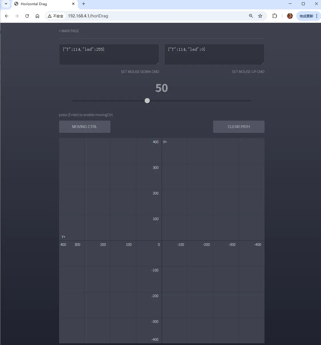 HORIZONTAL DRAG Control Interface
In this interface, you can control the position of the mouse on the drawing area to drive the end point of the robotic arm to move freely within the horizontal plane (X-Y plane).
For details, refer to the Coordinate System Description section.
3.4.1 Interface Description
The HORIZONTAL DRAG control interface is divided into the following functional areas from top to bottom:
| Area | Description | Function Overview |
|---|---|---|
| SET MOUSE DOWN CMD |
| Sets the JSON command executed when the left mouse button is pressed in the drawing area; defaults to turning on the LED light |
| SET MOUSE UP CMD |
| Sets the JSON command executed when the left mouse button is released in the drawing area; defaults to turning off the LED light |
| Progress Bar (Value Display) |
| Controls the position of the end point on the Z-axis (vertical height); can also be adjusted with the mouse wheel |
| MOVING CTRL |
| Button to enable/disable the drawing control mode |
| CLEAR PATH |
| Clears all movement traces on the drawing area |
| Drawing Area (X-Y Coordinate System) |
| Horizontal plane control area for the end point; the mouse position corresponds to the X / Y coordinates of the end point |


3.4.2 Usage Steps
When drawing control is enabled, the end point of the robotic arm will immediately move to the coordinate position where the mouse currently is.
Therefore, before enabling, make sure the mouse is not inside the drawing area to avoid collision or injury caused by sudden fast movement of the end-effector.
-
Enable Drawing Control
Press the
Enterkey on the keyboard, or click theMOVING CTRLbutton to enable drawing control mode.After successful enabling, the following prompt appears above the
MOVING CTRLbutton:movingCtrl: EnableAfter enabling, it is recommended to slowly move the mouse from the X+ side of the drawing area into the canvas, allowing the end-effector to follow to the target position at a slower speed, avoiding rapid movement due to a large position gap.
-
Control End-effector Movement
After moving the mouse into the drawing area (XY coordinate area), the end-effector will move in real time with the mouse position:
- The mouse position within the canvas corresponds to the X/Y coordinates of the end-effector in the horizontal plane.
- Scroll the mouse wheel upward → end-effector Z-axis rises; scroll downward → Z-axis lowers.
- You can also drag the progress bar at the top of the interface to adjust the Z-axis height; the current height value is displayed above the progress bar.
-
Draw Trajectories
- Hold the left mouse button and drag: LED turns on, and while the end-effector moves, a trajectory is drawn on the drawing area.
- Move the mouse without pressing any button: End-effector follows the movement, but no trajectory is left.
- Press the
Spacekey or click theCLEAR PATHbutton to clear all trajectories on the drawing area.
-
Disable Drawing Control
Press the
Enteragain or click theMOVING CTRLbutton to disable drawing control mode.After disabling, the following will appear above the
MOVING CTRLbutton:movingCtrl: Disable
After completing the above operations, you can click < MAIN PAGE in the upper-left corner to return to the main control interface and continue learning other functions of the robotic arm.
3.5 VERTICAL DRAG
Clicking VERTICAL DRAG will enter the dedicated control interface for this function (alternatively, you can also enter 192.168.4.1/vertDrag in the browser's address bar).
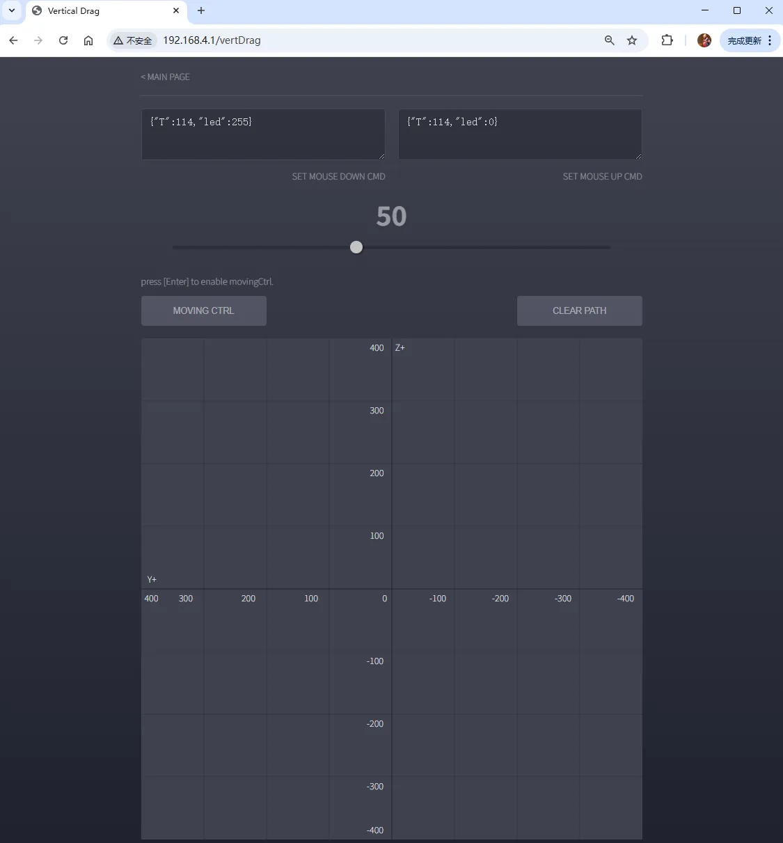 VERTICAL DRAG Control Interface
In this interface, you can control the position of the mouse on the drawing area to drive the end point of the robotic arm to move freely within the vertical plane (Y-Z plane).
For details, refer to the Coordinate System Description section.
3.5.1 Interface Description
The VERTICAL DRAG control interface is divided into the following functional areas from top to bottom:
| Area | Description | Function Overview |
|---|---|---|
| SET MOUSE DOWN CMD |
| Sets the JSON command executed when the left mouse button is pressed in the drawing area; defaults to turning on the LED light |
| SET MOUSE UP CMD |
| Sets the JSON command executed when the left mouse button is released in the drawing area; defaults to turning off the LED light |
| Progress Bar (Value Display) |
| Controls the position of the end point on the X-axis; can also be adjusted with the mouse wheel |
| MOVING CTRL |
| Button to enable/disable the drawing control mode |
| CLEAR PATH |
| Clears all movement traces on the drawing area |
| Drawing Area (Y-Z Coordinate System) |
| Vertical plane control area for the end point; the mouse position corresponds to the Y / Z coordinates of the end point |

3.5.2 Usage Steps
When drawing control is enabled, the end point of the robotic arm will immediately move to the coordinate position where the mouse currently is.
Therefore, before enabling, make sure the mouse is not inside the drawing area to avoid collision or injury caused by sudden fast movement of the end-effector.
-
Enable Drawing Control
Press the
Enterkey on the keyboard, or click theMOVING CTRLbutton to enable drawing control mode.After successful enabling, the following prompt appears above the
MOVING CTRLbutton:movingCtrl: EnableAfter enabling, it is recommended to slowly move the mouse from the Z+ side of the drawing area into the canvas, allowing the end-effector to follow to the target position at a slower speed, avoiding rapid movement due to a large position gap.
-
Control End-effector Movement
After moving the mouse into the drawing area (Y-Z coordinate area), the end-effector will move in real time with the mouse position:
- The mouse position within the canvas corresponds to the Y/Z coordinates of the end-effector in the horizontal plane.
- Scroll the mouse wheel upward → end-effector X-axis moves forward; scroll downward → X-axis moves backward.
- You can also drag the progress bar at the top of the interface to adjust the X-axis position; the current position value is displayed above the progress bar.
-
Draw Trajectories
- Hold the left mouse button and drag: LED turns on, and while the end-effector moves, a trajectory is drawn on the drawing area.
- Move the mouse without pressing any button: End-effector follows the movement, but no trajectory is left.
- Press the
Spacekey or click theCLEAR PATHbutton to clear all trajectories on the drawing area.
-
Disable Drawing Control
Press the
Enteragain or click theMOVING CTRLbutton to disable drawing control mode.After disabling, the following will appear above the
MOVING CTRLbutton:movingCtrl: Disable
After completing the above operations, you can click < MAIN PAGE in the upper-left corner to return to the main control interface and continue learning other functions of the robotic arm.
4. FEEDBACK INFORMATION
The FEEDBACK INFORMATION area is the window for "two-way communication" between the Web interface and the robotic arm, and also the entry point for directly sending JSON commands to control the arm.
JSON (JavaScript Object Notation) is a lightweight data format that organizes information as key:value pairs. It is highly readable and easy to transmit and parse between different systems. The robotic arm receives JSON-format commands to perform various actions.
Below is an example of a JSON command to control the robotic arm to move to a certain coordinate position:
{"T":1041,"x":200,"y":0,"z":150,"t":3.14}
Here "T" is the command type number, and the other fields are parameters for that command.
By sending different JSON commands, you can achieve more functions beyond the buttons on the web interface. For the specific meaning and parameter description of each command, please refer to [JSON Command Function Details].
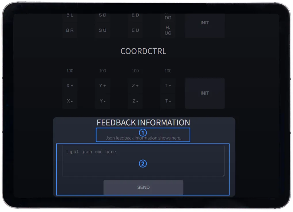 Feedback Area Annotation
- ① Status Information Display Area: Feedback from the sent JSON command will be displayed here;
- ② JSON Command Sending Area: Enter a JSON command and click
SENDto send it, achieving fine control of the robotic arm.
Some JSON commands return long feedback content, which may be not fully displayed in the status information display area. To view the full feedback, it is recommended to use HTTP request communication or serial communication.
There are two ways to send JSON commands on this interface:
-
Manual Command Entry:
① Enter a JSON command in the sending area, e.g.,
{"T":114,"led":255}② Click
SENDto send.③ The display area above shows the response from the robotic arm.
-
Use Shortcut Commands:
Below the FEEDBACK INFORMATION area, commonly used JSON commands are listed, each with an
INPUTbutton:① Click
INPUTto automatically fill the command into the input box of the sending area above.② After confirming or modifying the parameters, click
SENDto send.
The shortcut command area includes common operations such as querying the arm’s status and setting Wi-Fi mode. For first-time users, it is recommended to familiarize yourself with various JSON command formats via the shortcuts before attempting to write commands manually.
At this point, you have learned all functional modules of the Web control interface. If you wish to further control the robotic arm by sending JSON commands or using a Python program, please continue reading JSON Command Sending Methods.