Using the Development Tools
This tutorial introduces the installation and usage of the development tools, with a focus on uploading modified programs to the Servo Driver with ESP32 for secondary development based on the ST/SC series servo programs. The development tool used here is Arduino IDE. The following sections describe the installation and usage of the servo dependency libraries and the development environment in Arduino IDE.
1. Arduino Installation and Environment Setup
1.1 What is Arduino IDE
Arduino IDE (Integrated Development Environment) is an open-source code-based development platform with its own programming language and development environment. Arduino IDE provides a rich set of libraries, greatly simplifying the use of complex hardware and software platforms such as displays and sensors.
1.2 Installing Arduino IDE
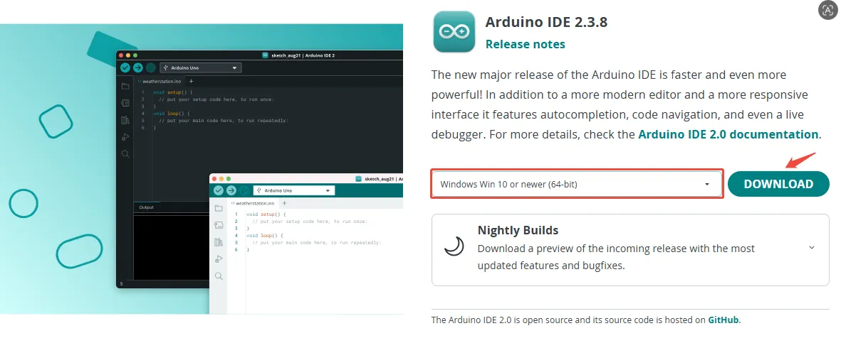
Downloading Arduino IDE
First, go to the Arduino website to download the latest version of the Arduino IDE installer. The official IDE supports downloads for different operating systems; choose according to your operating system. Here we download the Windows version. If already installed, skip to step two. The installation process is very simple; just keep clicking Next.
During installation, you will be prompted to install drivers; just click Install.
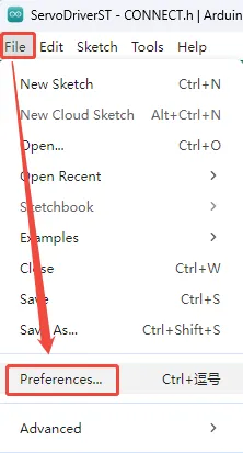
Setting Arduino IDE to a Different Language
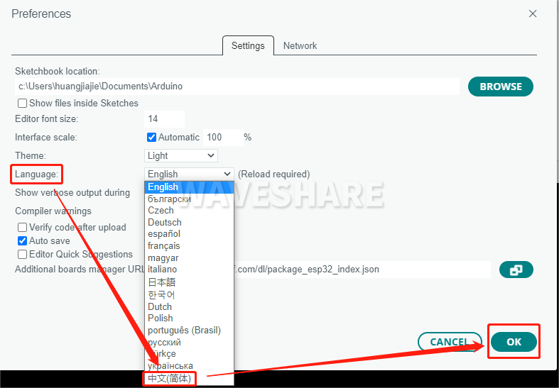
Upon completing the initial installation, the Arduino IDE interface will be in English. To change it to a different language, navigate to "File" → "Preferences".
In the "Language" field, select the desired language (e.g., Simplified Chinese), and click OK.
1.3 Installing the Development Environment
The main control module on the robot's driver board is ESP32, so we need to install the corresponding ESP32 board package in the Arduino IDE development environment. The steps are as follows:
-
Open Arduino IDE, click "File" → "Preferences".
-
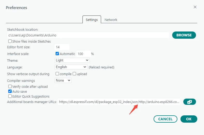
Add the following link in the "Additional Boards Manager URLs" field, then click "OK" to save the settings.
https://dl.espressif.com/dl/package_esp32_index.json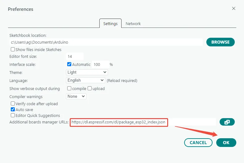 warning
If you need to add multiple board URLs, do not delete the ESP32 board support URL. You can add other URLs on separate lines; by default they are separated by commas.
For example, if you need to add the ESP8266 board URL, add it on a new line as shown:
https://dl.espressif.com/dl/package_esp32_index.json,http://arduino.esp8266.com/stable/package_esp8266com_index.json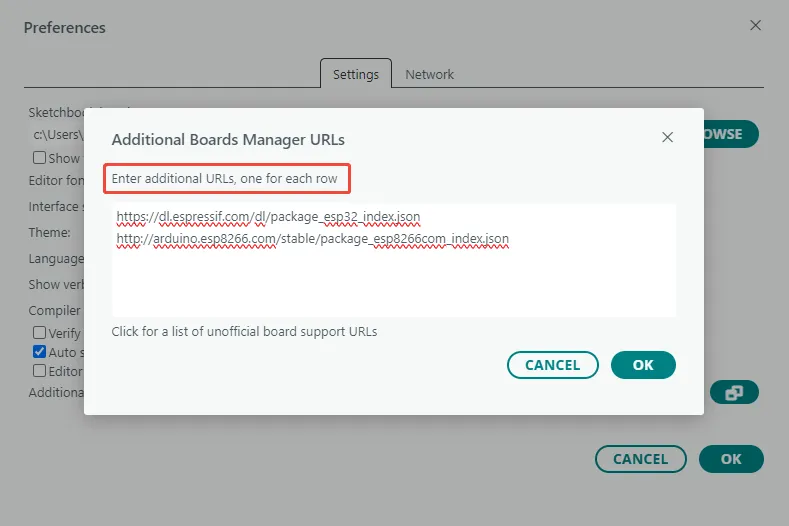
-
Download packages and extract it. In "This PC", navigate to the following path:
C:\Users\username\AppData\Local\Arduino15Replace "username" with your actual Windows username. Copy the extracted "packages" folder into the "Arduino15" folder.
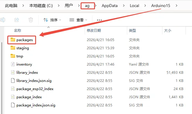
Under "Arduino15/packages/esp32/hardware/esp32", you can check that the installed ESP32 board support package version is 1.0.6.
 warning
The ST/SC series servo open‑source programs are written based on the ESP32 board support package version 1.0.x. Version 1.0.6 is recommended. If you use version 3.x or later, the ESP‑NOW receive callback interface may be incompatible, and you will encounter function type mismatch errors related to
esp_now_recv_cb_twhen uploading the program.
1.4 Installing Dependency Libraries
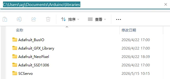
Download the dependency library files and extract them. Copy the extracted library folders to the Arduino user library directory (libraries). The default path is:
C:\Users\username\Documents\Arduino\libraries
Replace "username" with your actual Windows username.
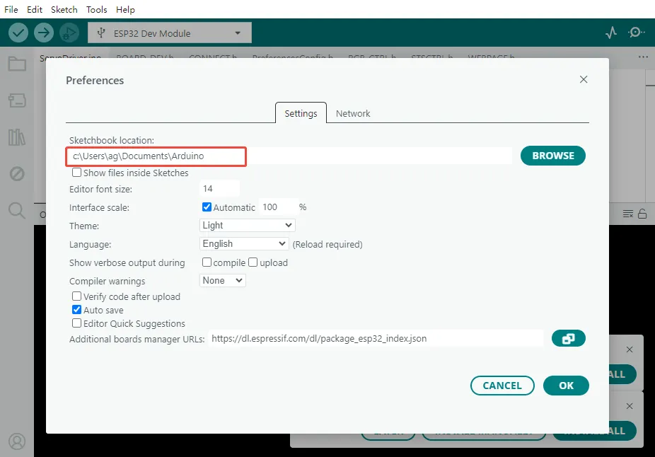
Open Arduino IDE, click "File" → "Preferences", and look at the "Sketchbook location". For example:
Sketchbook location:
C:\Users\ag\Documents\Arduino
Then the library directory is:
C:\Users\ag\Documents\Arduino\libraries
1.5 Uploading a Program
-
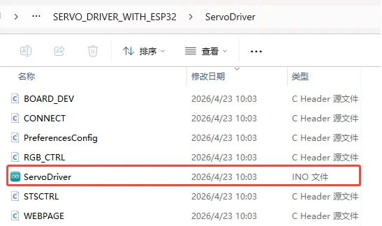
Download the SC series servo open‑source program, unzip it, and double‑click to open "ServoDriver.ino". Note that all files in this directory must be in the same folder.
 info
infoThe factory‑default program on the Servo Driver with ESP32 is the SC series servo open‑source program. If you are using ST series servos, please download the ST series servo open‑source program
-
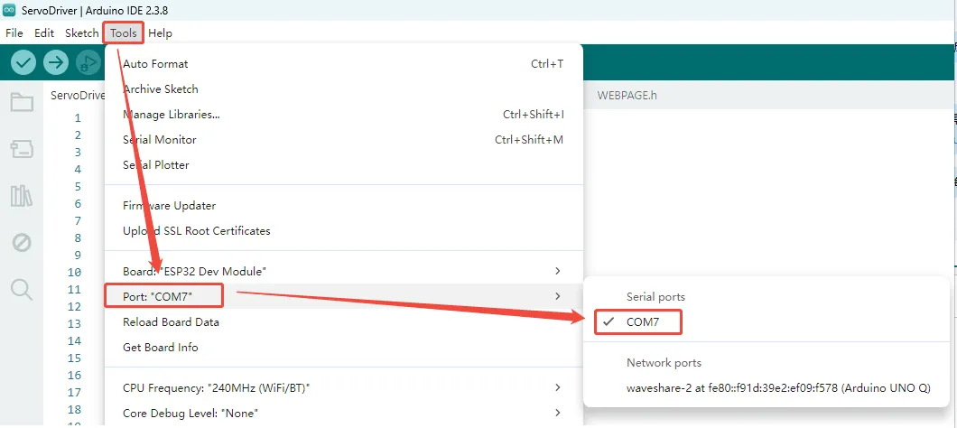
Click "Tools" → "Port" to see the currently available serial devices. Note the COM port on your PC; no need to click it (different computers may show different COM ports, and there may be none).
-
Connect the Servo Driver with ESP32 to the computer via a USB cable. Click "Tools" → "Port" again, observe the newly appeared serial port compared to step 2, and select that new COM port (in this example, the new COM port is COM7).
-
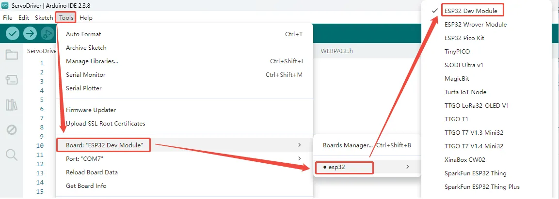
In Arduino IDE, click "Tools" → "Board" → "ESP32" → "ESP32 Dev Module".
-
Click "Tools". Other settings are as follows: (Partition Scheme is best set to Huge APP, PSRAM must be set to Enabled)

-
After all settings are complete, click the upload icon in the upper‑left corner to start uploading.
 warning
If you encounter issues during upload and need to reinstall or change the Arduino IDE version, you must completely uninstall Arduino IDE. After uninstalling the software, manually delete all contents in the folder
C:\Users\username\AppData\Local\Arduino15(hidden files need to be visible), then download and install again.
2. Advanced Configuration
2.1 Modifying the Maximum Scan ID
To detect connected servos, the program sends Ping commands sequentially starting from ID 1 up to the set maximum ID. If the servo IDs are large or many servos are connected, you can increase the MAX_ID value. If you know the servo IDs are in a smaller range, you can decrease this value to shorten the scan time.
Modify the following parameter in ServoDriver.ino:
// Set the maximum ID to scan
int MAX_ID = 20;
The default MAX_ID is 20, with a maximum supported value of 253. Larger values increase scan time.
2.2 ESP-NOW Communication Configuration
Driver boards communicate wirelessly via ESP‑NOW. The default program supports one‑to‑one control, and you can extend it to one‑to‑many or many‑to‑many communication as needed.
In ESP‑NOW communication, each device has a unique MAC address. Before establishing communication, the Leader (controller) needs to know the MAC address of the Follower (controlled device) in order to send control data to the designated device.
The driver board supports the following three operation modes:
| Mode | Description |
|---|---|
| Normal | Normal mode, does not participate in ESP‑NOW |
| Leader | Controller, sends control data to other devices |
| Follower | Controlled device, receives and executes commands |
When using one driver board to control another, configure one as Leader and the other as Follower.
2.2.1 Obtaining the Follower's MAC Address
First, connect the board that will act as the Follower. After power‑up, the board automatically obtains its own MAC address and displays it on the first line of the OLED screen. Record this MAC address; it will be needed when configuring the Leader later.
2.2.2 Setting Follower Mode
Open ServoDriver.ino and change DEFAULT_ROLE to 2:
// set the default role here.
// 0 as normal mode.
// 1 as leader, ctrl other device via ESP-NOW.
// 2 as follower, can be controled via ESP-NOW.
#define DEFAULT_ROLE 2
Compile and upload the program to the Follower board. After upload, the board will automatically enter Follower mode on every power‑up.
This step is not mandatory; you can also switch the working mode manually via the Web configuration page.
2.2.3 Configuring the Target MAC Address and Leader Mode
Connect the board that will act as the Leader, open ServoDriver.ino. Change broadcastAddress[] to the Follower's MAC address, remembering to prefix each byte with 0x.
// the MAC address of the device you want to ctrl.
uint8_t broadcastAddress[] = {0x94, 0xB5, 0x55, 0x1D, 0xD1, 0x0C};
The above is an example; each device has a different MAC address, so modify it according to your actual situation.
Change DEFAULT_ROLE to 1:
// set the default role here.
// 0 as normal mode.
// 1 as leader, ctrl other device via ESP-NOW.
// 2 as follower, can be controled via ESP-NOW.
#define DEFAULT_ROLE 1
Compile and upload the program to the Leader board. After upload, the Leader will automatically establish ESP‑NOW communication with the specified Follower.
After connecting servos with the same IDs to both devices, refer to the Web Usage Tutorial to control the servos on the Leader board. The Leader will send the ID and position data of the currently selected servo (Active Servo) to the Follower. Upon receiving the data, the Follower will control the servo with the corresponding ID to move synchronously.
-
This only works in Servo Mode. If the servos are in Motor Mode, position synchronization is not possible because target angles cannot be directly controlled.
-
It is recommended to use different Wi‑Fi names. When using multiple driver boards simultaneously, set a unique Wi‑Fi SSID for each board. Otherwise, when searching for and connecting to Wi‑Fi from phones, computers, etc., it may be difficult to distinguish between boards, leading to accidental connections. For how to modify the SSID, refer to 2.3 Wi‑Fi: AP and STA Modes.
2.3 Wi‑Fi: AP and STA Modes
The driver board supports two Wi‑Fi operation modes: AP (Access Point) and STA (Station).
| Mode | Description |
|---|---|
| AP | The board creates a Wi‑Fi hotspot; phones or computers can connect directly to it to access the Web interface |
| STA | The board connects to an existing Wi‑Fi network and joins that local network |
2.3.1 Configuring AP Mode
In AP mode, the board creates a Wi‑Fi hotspot. You can modify the hotspot name (SSID) and password in ServoDriver.ino:
// WIFI_AP settings.
const char* AP_SSID = "ESP32_DEV";
const char* AP_PWD  = "12345678";
After modification, set DEFAULT_WIFI_MODE to 1:
// set the default wifi mode here.
// 1 as [AP] mode, it will not connect other wifi.
// 2 as [STA] mode, it will connect to know wifi.
#define DEFAULT_WIFI_MODE 1
Upload the program; the board will automatically create the corresponding Wi‑Fi hotspot on power‑up.
2.3.2 Configuring STA Mode
In STA mode, the board connects to a specified Wi‑Fi network. In ServoDriver.ino, enter the target Wi‑Fi name and password:
// WIFI_STA settings.
const char* STA_SSID = "OnePlus 8";
const char* STA_PWD  = "40963840";
Then set DEFAULT_WIFI_MODE to 2:
// set the default wifi mode here.
// 1 as [AP] mode, it will not connect other wifi.
// 2 as [STA] mode, it will connect to know wifi.
#define DEFAULT_WIFI_MODE 2