Product Usage
The factory‑default firmware on the Servo Driver with ESP32 is designed for our SC series servos.
If you are using SC series servos, after connecting the servos to the driver board and supplying appropriate power, you can connect to the board's Wi‑Fi and control the servos via the web interface. See the Web Usage Tutorial on this page for details.
If you are using our ST series servos, you will need to flash the firmware intended for ST series servos before you can control them via the web interface.
This driver board supports both ST and SC series bus servos, with dedicated flashable firmware provided for each. You can flash the firmware using the ESP32 download tool without installing Arduino IDE or any dependency libraries. After flashing, you can perform operations such as servo ID configuration, mode switching, and motion control via the web interface. The following sections describe the firmware flashing steps and web usage tutorial for both ST and SC series servos.
1. Firmware Flashing
1.1 ST Series Servos
Click to download the ST Series Servo ESP32 Download Tool. After extraction, double‑click to open flash_download_tool_3.9.5.exe. Two windows will appear: one is a black terminal window showing the tool's status, and the other is the main UI where you perform the operations.
In the "DOWNLOAD TOOL MODE" interface, select ChipType as ESP32 and WorkMode as Factory (this uses binary files with auto‑adapted relative paths; no manual input is required). Click OK to confirm.

Keep the LockSettings checkbox selected (this supports flashing up to 8 boards simultaneously). Connect the driver board to your computer via USB, click the COM option, and select the newly detected COM port. BAUD sets the flashing speed, up to 921600 (higher speed means faster flashing).
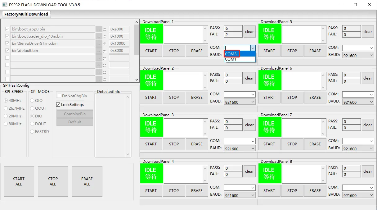
After confirming the settings, click START to begin flashing. When the interface shows FINISH, the flashing is successful.


After flashing, disconnect the USB connection between the board and your computer, connect the servos, and power the board. You can then start controlling the ST series servos.
1.2 SC Series Servos
Click to download the SC Series Servo ESP32 Download Tool, then follow the same flashing steps described for the ST series servos. After flashing, connect the servos to the driver board and power it on to start controlling SC series servos.
2. Web Usage Tutorial
This section uses the ST series servo example firmware to illustrate the web interface.
2.1 Connecting Servos and Power
Using the ST3215 Servo as an example: after connecting the servo to the driver board, power the board via the 5.5 × 2.1 mm DC jack with 6 – 12.6 V (12 V recommended). This power input directly supplies the servos.
The Servo Driver with ESP32 has a maximum current rating of 5 A. If you are using a large number of servos, power them in separate groups to prevent the board from being damaged by excessive current.
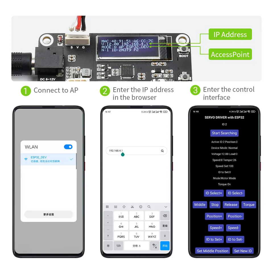
2.2 Connecting to the Board's Wi‑Fi Hotspot
- After power‑up, the board automatically creates a Wi‑Fi hotspot with the default SSID ESP32_DEV and password 12345678.
- Use your phone or computer to connect to this Wi‑Fi. Since this network does not provide Internet access, some devices may automatically switch to other saved Wi‑Fi networks. If this happens, reconnect to the ESP32_DEV network; after a successful reconnection, the connection should remain stable.
- It is recommended to use Google Chrome. Enter 192.168.4.1 in the address bar to access the Web control interface.
2.3 Servo Scanning
- The board automatically scans for servos at power‑up. If you connect servos after the board is already powered on, click "Start Searching" on the interface to rescan.
- Our servos have a default ID of 1. When connecting multiple servos to the board, you must change their IDs to avoid conflicts; otherwise, they may not be detected. When changing a servo ID, it is recommended to connect only the single servo that needs its ID changed.
- By default, the board scans for servo IDs from 0 to 20. If you are using a servo with an ID greater than 20, you must modify the
MAX_IDvalue in the source fileServoDriverST.ino(the maximum valid value is 253) and re‑flash the firmware. - After scanning, the interface displays all currently connected servo IDs, allowing you to perform subsequent operations.
2.4 Core Function Operations
The buttons on the web interface and their functions are described below. All operations apply to the currently selected Active ID (the currently selected servo ID):