Getting Started
System Preparation and Screen Configuration
Some earlier versions of the Arduino UNO Q system may lack the drivers and device tree files required by the screen, causing the screen to fail to work properly. Please follow the steps below to check the system and complete the screen configuration.
Configure via Arduino App Lab
Please use Arduino App Lab 0.8.0 or later. If you are using an older version, update it first before configuring the expansion board.
-
Open Arduino App Lab on your computer. For detailed operations, please refer to the App Lab Usage. Use a Type-C cable to connect the UNO Q to the computer.
-
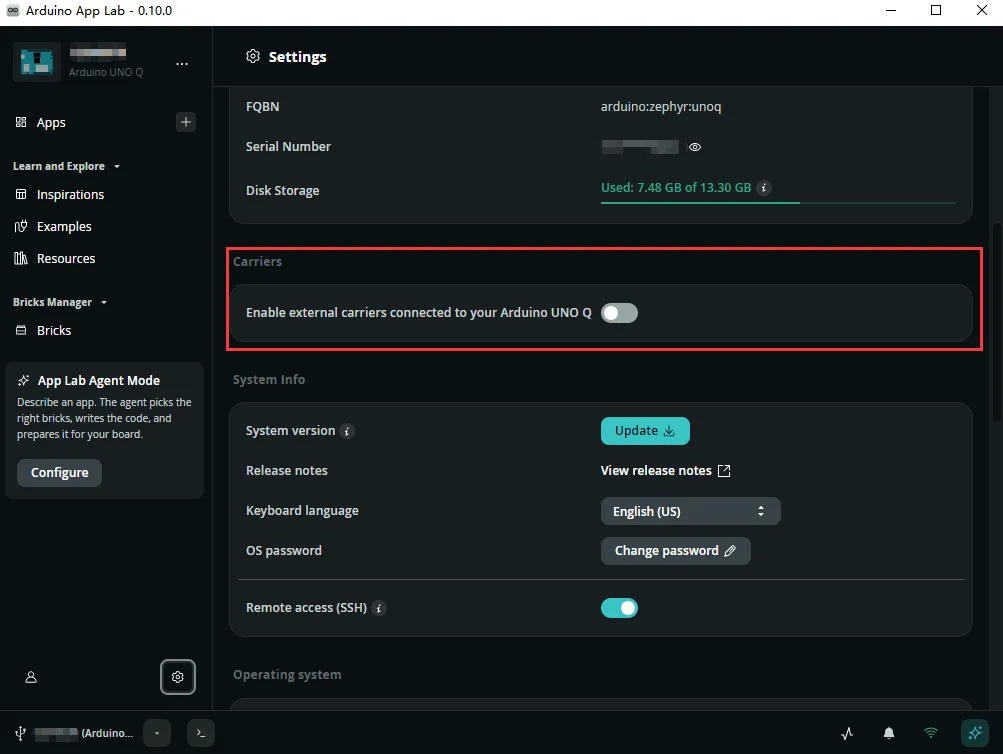
After completing the initial setup and account password configuration as prompted, click the Settings (⚙) icon in the lower left corner of Arduino App Lab to enter the Settings page, find the Carriers option, and enable Enable external carriers.
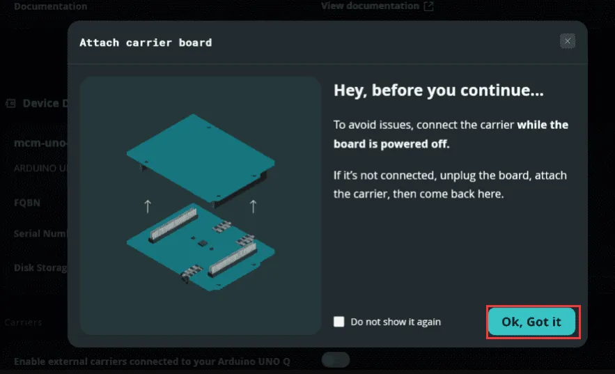
The following prompts may appear when enabling:
-
Attach carrier board: Please confirm that the UNO Q has been powered off and the screen expansion board has been correctly installed according to the Hardware Connection and Interface Description. After confirming, click "Ok, Got it" to continue.
-
Update required: This indicates that the current system version does not support the Media Carrier. Click "Update Board" and follow the on-screen prompts to complete the system update and restart. After updating, return to "Settings" > "Carriers" and enable the expansion board feature.

If the system update prompt does not appear, you can continue directly with the subsequent configuration.
-
-
Confirm that Enable external carriers is enabled, and select
10-dsi-touch-ain the display device options. If no camera is connected, set both CAMERA0 and CAMERA1 tonone.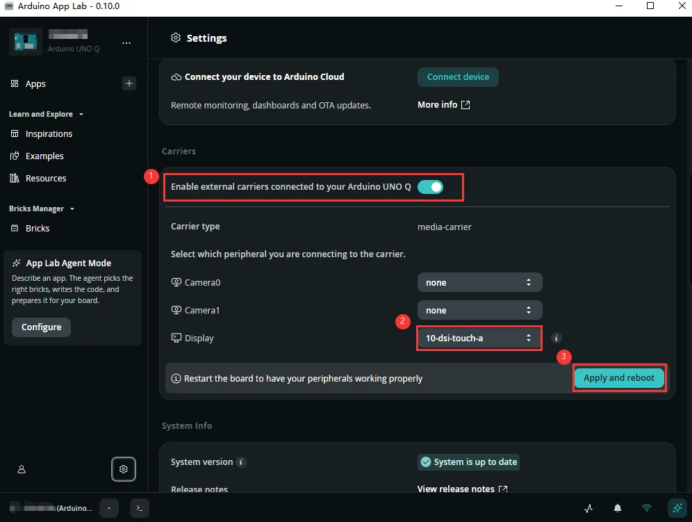
-
Click Apply and Reboot, and after the UNO Q restarts, check whether the screen display and touch functions work properly.
- Before configuring the screen, please make sure that the UNO Q and the screen are correctly connected according to the Hardware Connection and Interface Description.
- During the update, keep the UNO Q power supply and network connection stable, and avoid power interruption.
- If you cannot complete the system update through App Lab, first back up the applications and personal files on the mainboard, then refer to the Arduino Official System Flashing Guide. Reflashing will erase the data stored on the mainboard.
Configure via Command Line (Optional)
You can also enter the UNO Q terminal via SSH or ADB and configure the screen using the command line.
1. View supported devices
sudo arduino-linux-config carrier list
Confirm that the device list contains media-carrier, and that the display device options contain 10-dsi-touch-a.
2. Enable the screen
When no camera is connected, run:
sudo arduino-linux-config carrier enable media-carrier camera0=none camera1=none display=10-dsi-touch-a
If a compatible IMX219 camera is connected to the CAMERA0 interface, you can use:
sudo arduino-linux-config carrier enable media-carrier camera0=type1-2lanes camera1=none display=10-dsi-touch-a
3. Check the configuration
sudo arduino-linux-config carrier show media-carrier
Confirm that the display configuration for the next boot is 10-dsi-touch-a.
4. Restart the device
sudo reboot
After the UNO Q restarts, check the screen display and touch functions.
Camera Usage
- This product only supports the IMX219 camera. If you do not need to use a camera, you can skip this section.
- When both CAMERA0 and CAMERA1 are enabled, but only one camera is connected, please connect the camera to CAMERA0.
Enable the Camera
-
Turn off the UNO Q and disconnect the power. Connect the camera to CAMERA0 according to the Hardware Connection and Interface Description, and confirm the cable orientation is correct before supplying power.
-
In App Lab's "Settings" > "Carriers", set CAMERA0 to
type1-2lanes, CAMERA1 tonone, keep the display as10-dsi-touch-a, and click "Apply and Reboot".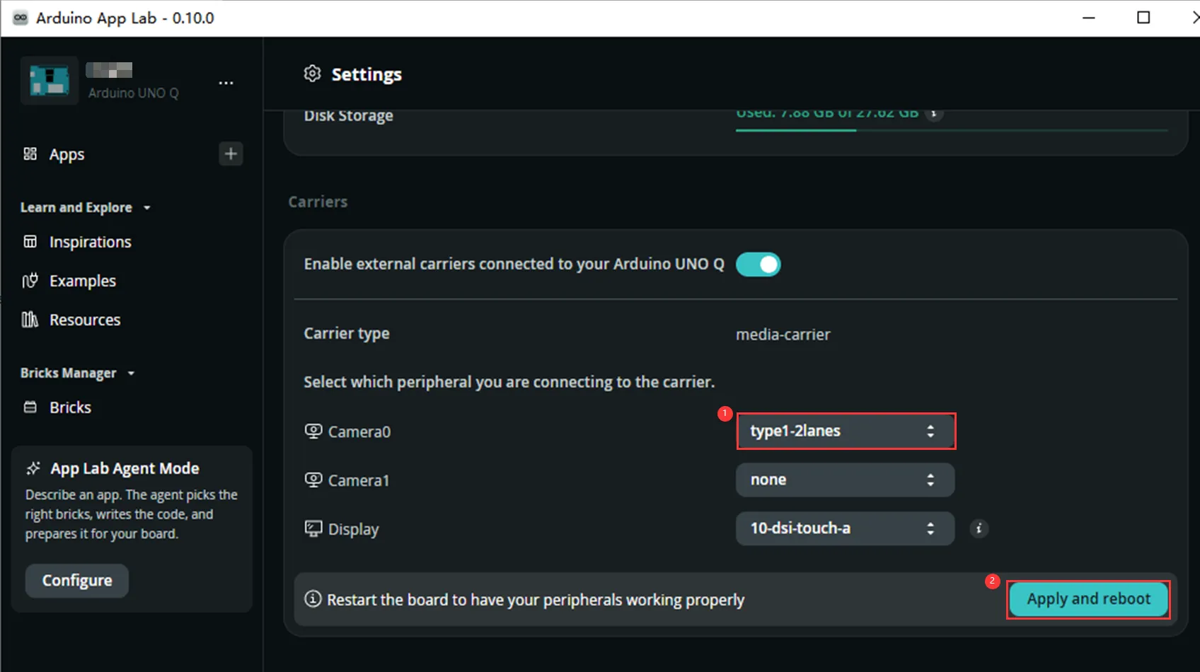
You can also run the following commands in the UNO Q terminal to complete the configuration.
Using one camera:
sudo arduino-linux-config carrier enable media-carrier camera0=type1-2lanes camera1=none display=10-dsi-touch-a
sudo reboot
Using two cameras:
sudo arduino-linux-config carrier enable media-carrier camera0=type1-2lanes camera1=type1-2lanes display=10-dsi-touch-a
sudo reboot
Install and Open Cheese
When you need to take photos or record videos on the desktop, install Cheese in the UNO Q terminal:
sudo apt update
sudo apt install cheese -y
After the installation is complete, open the application from "Applications" > "Multimedia" > "Cheese" on the device desktop.
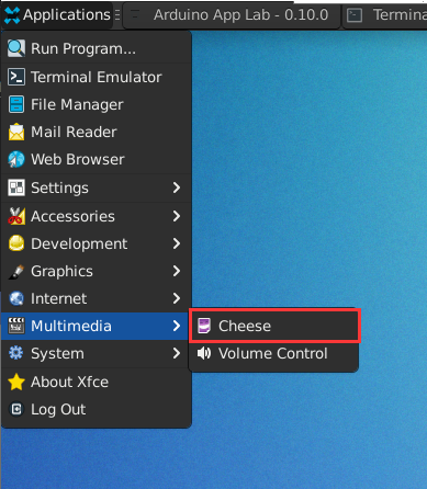
You can also run the following command in a terminal that is already logged into the desktop, without sudo:
cheese
Set the Resolution and Take Photos, Record Videos
Before use, exit other programs that are occupying the camera. When you need to test two cameras, first enable CAMERA0 and CAMERA1 according to the steps above.
-
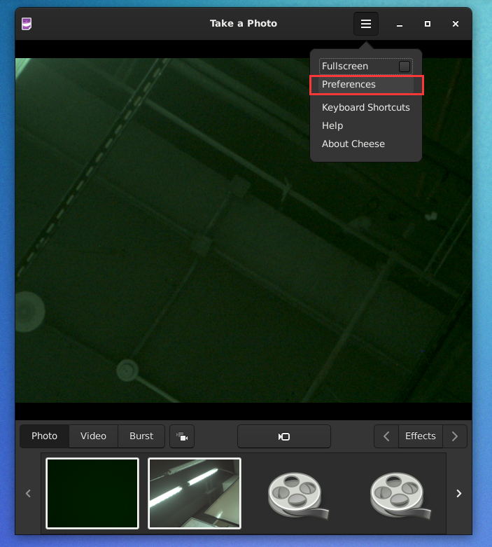
Open the menu in the upper right corner of Cheese, select "Preferences", and go to the "Webcam" page.
-
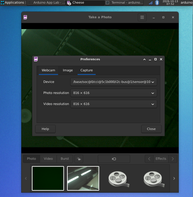
In "Device", select the camera, and set both "Photo resolution" and "Video resolution" to 816 × 616.
-
Close Preferences and wait a few seconds to observe the image. If capture previously failed, exit and reopen Cheese.
-
In "Photo" mode, click the capture button and confirm that the photo can be opened.
-
Switch to "Video" mode, click record, wait about 4 seconds, then click stop and confirm that the recording can be played.
-
When two cameras are connected and enabled, return to Preferences, select the other camera, check both resolutions again, and repeat the photo and video tests.
Photos are saved by default to ~/Pictures/Webcam/, and recordings are saved by default to ~/Videos/Webcam/. If the system pictures or videos directory has been renamed, or a different save location has been set, the actual local directory shall prevail.
Audio Usage
Graphical Interface Configuration
The baseboard provides 2 3.5 mm audio interfaces and has two built-in speakers, which can be used for audio input and output.
-
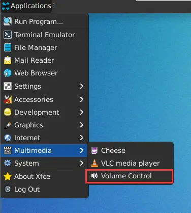
Open "Volume Control" from "Applications" > "Multimedia" on the device desktop.
-
Check the "Profile" configuration in "Configuration". After selecting the desired configuration, check the actual output in "Output Devices", unmute, and set a lower volume first.
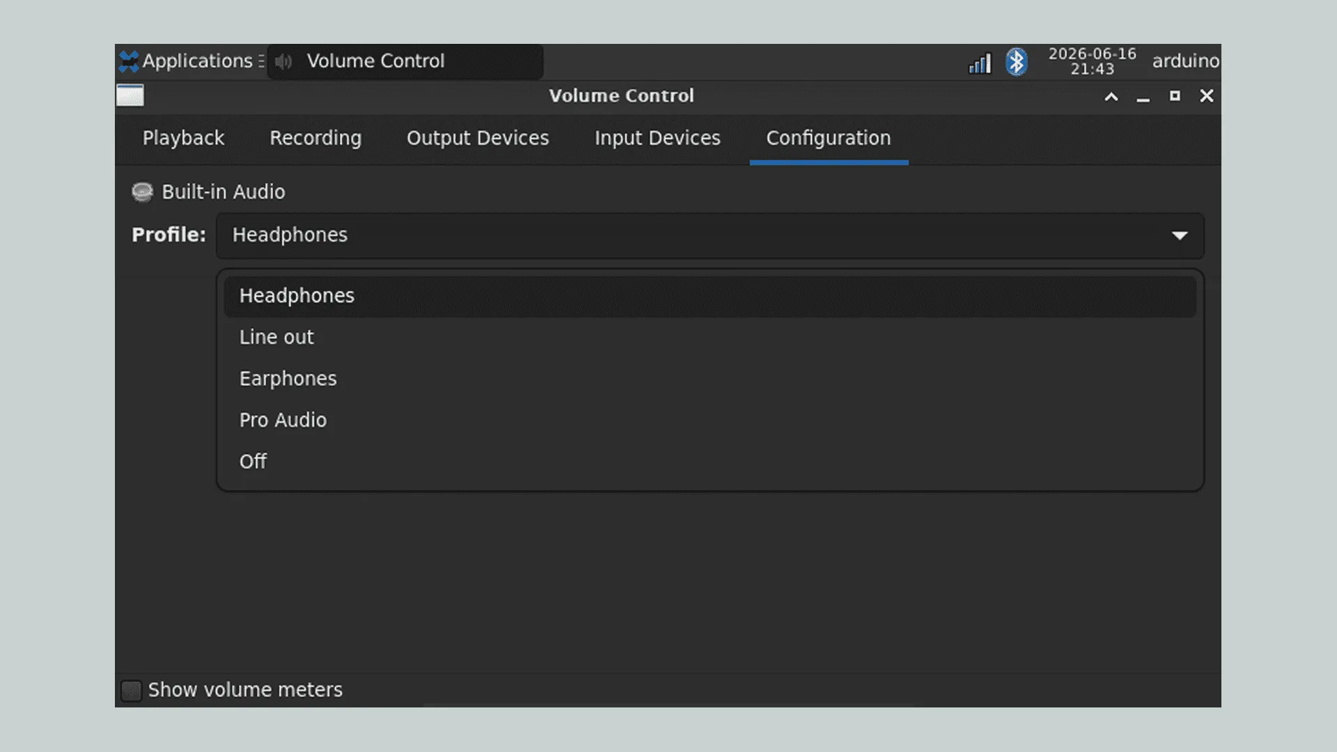
| Interface / Mode | Type | Function |
|---|---|---|
| Line Out | 4Pin speaker interface | Line-level audio output, mono |
| Headphones | 3.5 mm audio interface | Supports microphone input and headphone output, stereo |
| Earphones | 3.5 mm audio interface | Headphone audio output, mono |
| Pro Audio | Audio configuration mode | Supports professional audio applications and multi-channel audio input/output |
| Off | Audio configuration mode | Disables the current audio device |
- Play an audio file, confirm in "Playback" that the application uses the desired output, and then check whether the headphones have sound. When you need to use a microphone, select the corresponding input in "Input Devices", unmute, and check whether the level changes with sound.
Switch Audio Output via Command Line
The following commands only switch the switch at the output end. They are applicable to systems where the basic playback routing has already been configured and the corresponding control items exist on sound card 0. First use aplay -l and amixer -c 0 controls to verify the sound card and control items; if the card number differs, replace 0 in the commands. If the playback routing has not yet been configured, prefer using the graphical interface above. You cannot determine that there is sound based only on a successful switch command.
Switch to Earphones:
amixer -c 0 cset name='LO_RDAC Switch' off
amixer -c 0 cset name='EAR_RDAC Switch' on
Switch to Line Out:
amixer -c 0 cset name='EAR_RDAC Switch' off
amixer -c 0 cset name='LO_RDAC Switch' on
Audio Input
When performing a microphone recording test, connect the microphone to the MIC-IN/HPH interface. Do not mistakenly connect it to the Earphones Out interface, as this may prevent recording.
After the connection is complete and the corresponding input is selected and enabled in "Volume Control", you can test microphone recording. The following steps assume that the recording routing has already been initialized; adjusting only the recording gain cannot enable the ADC and recording channel. If it has not been initialized, first complete the routing according to the audio configuration of the current image.
1. Install audio tools
Open a terminal and run the following commands to install the ALSA tools:
sudo apt update
sudo apt install alsa-utils -y
2. View audio devices
Run the following commands to view the recording and playback devices recognized by the system:
arecord -l
aplay -l
Confirm the sound card number and device number corresponding to the microphone. The following uses sound card 0 and recording device 2 as an example; if the actual numbers differ, modify the subsequent commands accordingly.
3. Set the microphone recording gain
After confirming that this control item exists on sound card 0 and that the allowed value range includes 70, run the following command to set the recording gain:
amixer -c 0 cset name='TX_DEC0 Volume' 70
4. Record audio
If recording.wav already exists in the current account's home directory, use a different file name first. Run the following command to record 5 seconds of audio and save it as a WAV file:
arecord -D plughw:0,2 -f S32_LE -c 1 -r 48000 -d 5 "$HOME/recording.wav"
5. Play the recording
After recording is complete, run the following command to play the recording file:
aplay "$HOME/recording.wav"
If recording reports Device or resource busy, it means the recording device may be in use by another audio service or application. Please close the software that is using the microphone, or check the device usage of the current audio service.
RGB Status Light Usage
This product is equipped with 4 sets of RGB status indicator lights. Each set can independently control the red, green, and blue color channels, and can be used for device status indication and application feedback.
Control the RGB LED
Run the following commands in the UNO Q terminal, using the first set of RGB LEDs as an example:
Light up the red LED:
echo none | sudo tee /sys/class/leds/media-carrier:red1/trigger
echo 1 | sudo tee /sys/class/leds/media-carrier:red1/brightness
Light up the green LED:
echo none | sudo tee /sys/class/leds/media-carrier:green1/trigger
echo 1 | sudo tee /sys/class/leds/media-carrier:green1/brightness
Light up the blue LED:
echo none | sudo tee /sys/class/leds/media-carrier:blue1/trigger
echo 1 | sudo tee /sys/class/leds/media-carrier:blue1/brightness
Turn off the first set of RGB LEDs:
for color in red green blue; do
    echo 0 | sudo tee /sys/class/leds/media-carrier:${color}1/brightness
done
Replace the number 1 at the end of the device name with 2, 3, or 4 to control the other sets of RGB LEDs. Different color channels can be lit at the same time to achieve color mixing.
Turn Off All RGB LEDs
Run the following command to turn off all color channels of the 4 sets of RGB LEDs:
sudo sh -c '
for n in 1 2 3 4; do
    for color in red green blue; do
        path="/sys/class/leds/media-carrier:${color}${n}"
        echo none > "$path/trigger"
        echo 0 > "$path/brightness"
    done
done
'