User Guide
Driver Installation
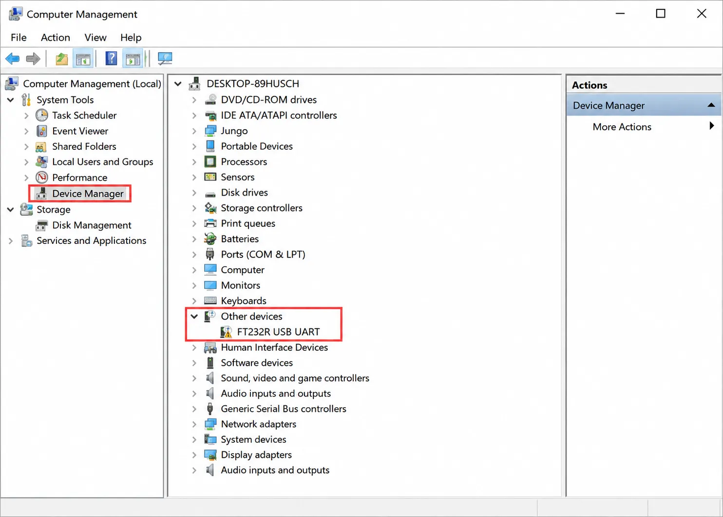
The USB TO RS485 (C) uses the FT232RNL chip. Most systems will automatically recognize it as a virtual COM port. If no available COM port appears in Device Manager, or if the serial device shows a yellow exclamation mark, manually install the FTDI VCP driver.
Manual Installation on Windows
-
Method 1: Download Driver Genius from the Internet and let it automatically detect and install the driver.
-
Method 2: Install the driver manually (the following uses Windows 7 as an example).
-
Connect the device to the computer via USB. In Device Manager, if the COM port has a yellow exclamation mark, the driver is not installed.
-
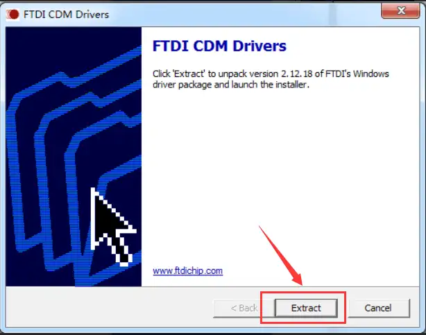
Download the software package from the official wiki. Double-click the application and click Extract:
-
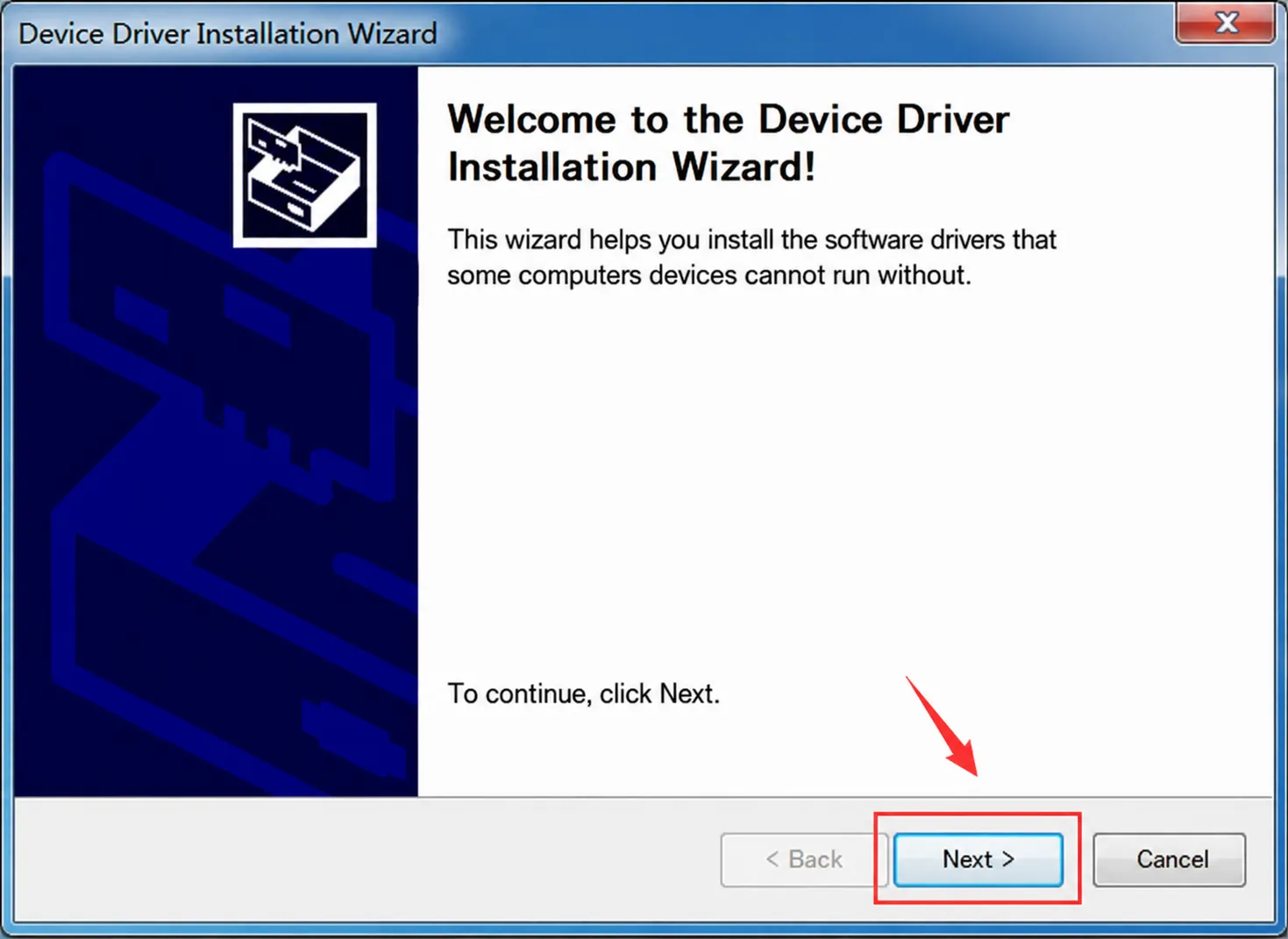
Click Next:
-
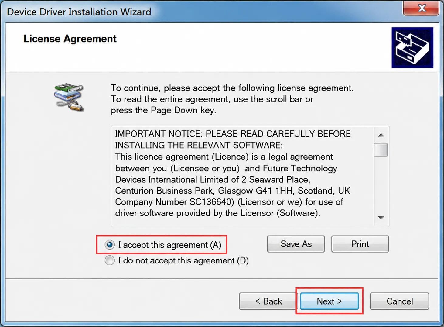
Check "I accept this agreement", then click Next:
-
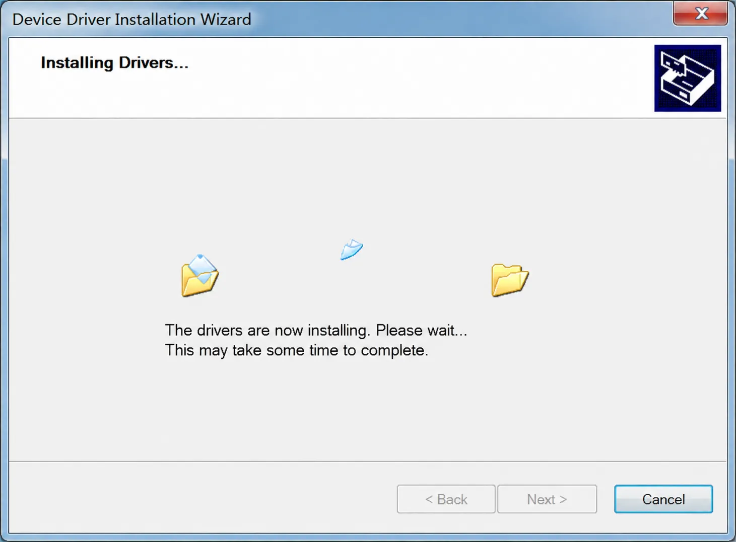
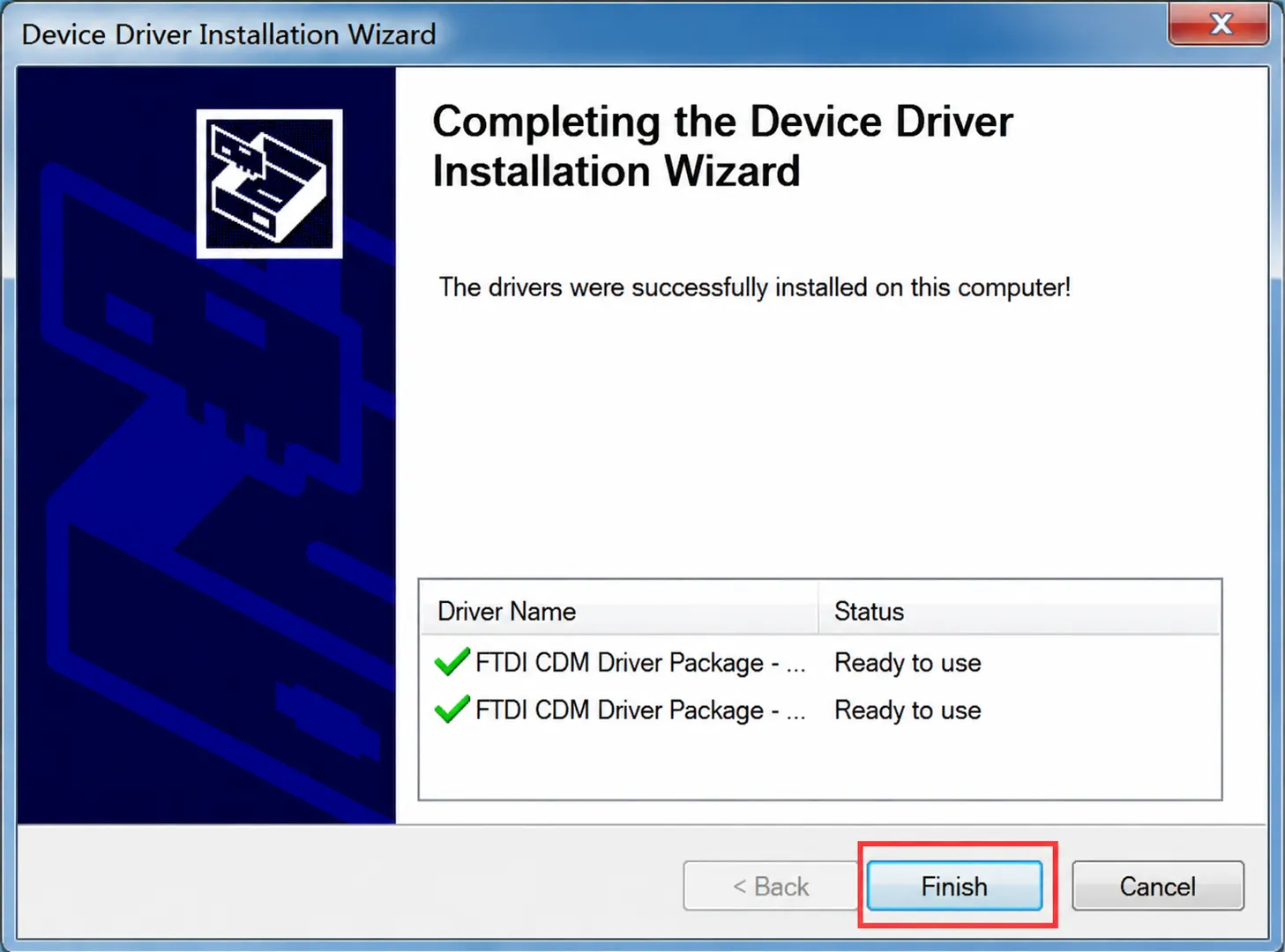
Wait for the installation to complete, then click Finish:
-
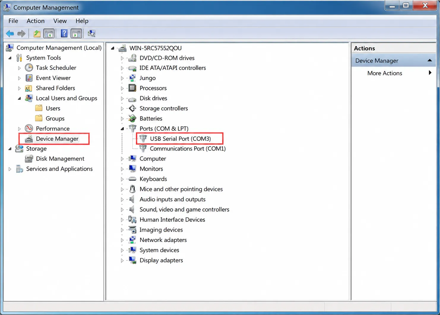
Now check Device Manager; the COM port should be available for normal use.
RS485 Wiring
Connect the USB TO RS485 (C) to the target RS485 device:
| USB TO RS485 (C) | Target RS485 Device |
|---|---|
| A+ | A / 485+ |
| B- | B / 485- |
| GND | GND (connect as needed) |
For short distances and low-interference environments, only A+ and B- may be sufficient for communication. For long-distance, multi-node, or high-interference environments, it is recommended to connect GND as a reference ground and to use appropriate termination resistors based on the bus topology.
RS485 Communication Test
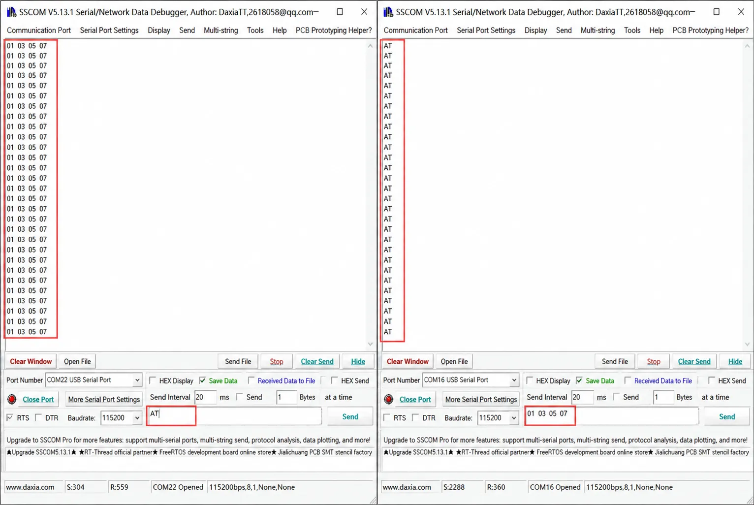
You can interconnect two USB TO RS485 converters or connect to a target RS485 device for testing.
- Connect A+ to A+, B- to B-, and GND if necessary.
- On the computer, open a serial debug assistant such as SSCOM.
- Select the appropriate COM port and set the same baud rate, data bits, parity, and stop bits.
- Send test data and observe the TXD/RXD LEDs and the receive window.
- If communication fails, try swapping A+ / B-, lowering the baud rate, checking termination resistors, and inspecting cable shielding and grounding.
Modbus Device Communication
The USB TO RS485 (C) is a physical-layer interface converter; it does not have a built-in Modbus master or slave protocol stack. When connecting to Modbus RTU devices, the Modbus protocol must be implemented on the PC, industrial computer, single-board computer, or host software, and then the module is used to send and receive RS485 data.
Typical test procedure:
- Connect A / B / GND to the Modbus RTU device.
- Confirm the slave address, baud rate, parity, data bits, and stop bits.
- Use Modbus Poll, a serial debug assistant, or a custom host program to send Modbus RTU commands.
- Refer to the slave device protocol manual to confirm register addresses, function codes, and data formats.
Precautions for Isolated Applications
- The isolated design reduces interference coupling between the host side and the field side, but does not replace proper field grounding, shielding, and lightning protection.
- Twisted-pair cable is recommended for the RS485 bus. Shielded twisted-pair cable is recommended for long-distance wiring.
- 120 Ω termination resistors can be installed at both ends of the bus depending on communication distance and speed. If short-distance communication is abnormal, try removing termination.
- For multi-node communication, a daisy-chain topology is recommended; avoid long star-type branches. When wiring near interference sources such as high-voltage equipment, frequency converters, and motors, increase separation distance or adopt shielding, grounding, and lightning protection measures.