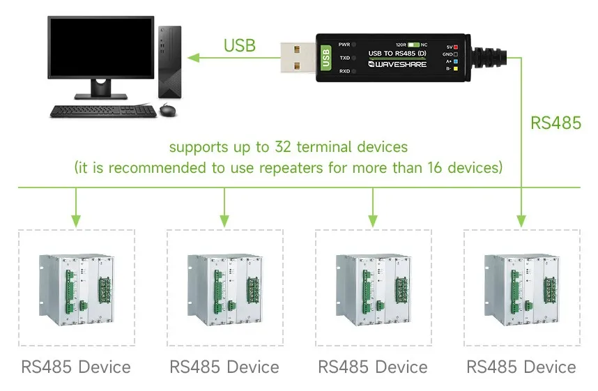
User Guide
Driver Installation
The USB TO RS485 (D) uses the FT232RNL chip. After the operating system recognizes the device, it will be used as a virtual serial port. If the system does not generate a serial device, install the FTDI Virtual COM Port (VCP) driver for your operating system.
The images below show the FTDI driver installation interface on Windows. The interface may vary depending on the driver version or operating system version.
Windows Manual Installation
-
Connect the converter to your computer. If the serial device in Device Manager shows a yellow exclamation mark, the driver is not properly installed.
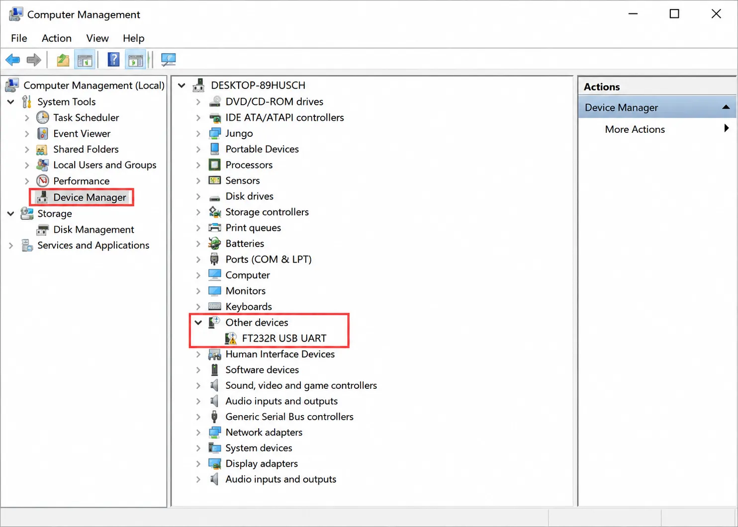
-
Download the driver for your operating system from the FTDI VCP driver page. Run the Windows installer and extract the installation files as prompted.
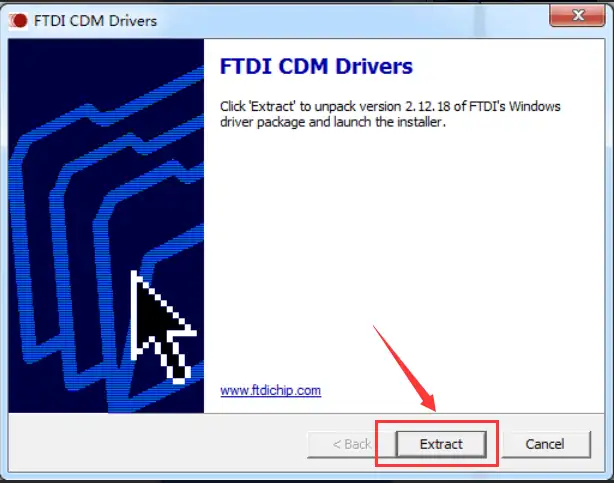
-
Read the license agreement, accept the terms, and proceed with the installation.
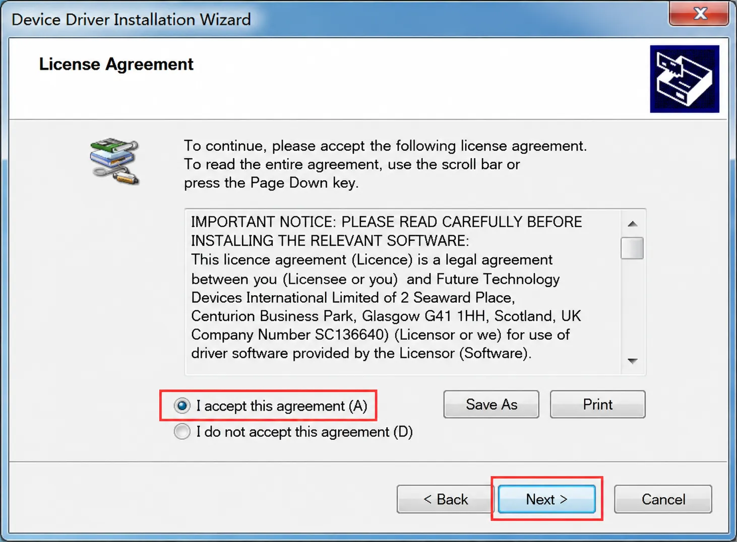
-
After installation is complete, unplug and reconnect the converter. Confirm the COM port number under "Device Manager" > "Ports (COM & LPT)".
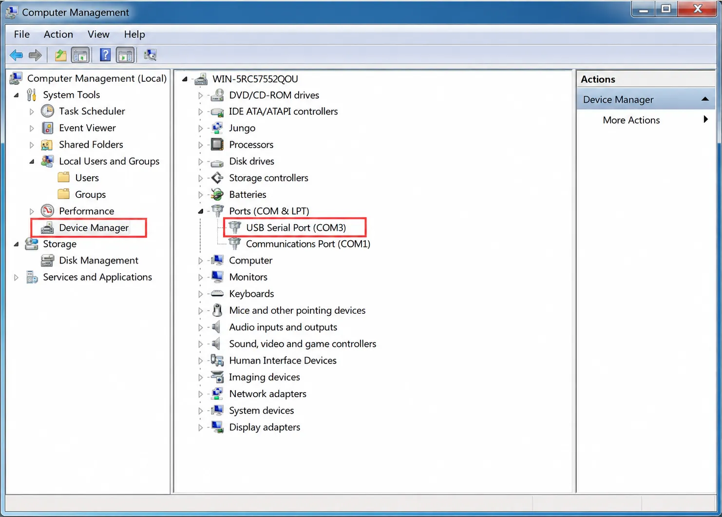
On Linux and macOS, confirm the device name in the system serial device list.
RJ45 Wiring
The RJ45 interface on this product uses the T568B wiring scheme, but it carries RS485 signals and power, not Ethernet data.
| Pin | T568B Color | Signal |
|---|---|---|
| 1 | White/Orange | A |
| 2 | Orange | B |
| 3 | White/Green | NC |
| 4 | Blue | 5 V |
| 5 | White/Blue | 5 V |
| 6 | Green | NC |
| 7 | White/Brown | GND |
| 8 | Brown | GND |
Pins 4 and 5 provide 5 V auxiliary power output with a maximum output current of 100 mA.
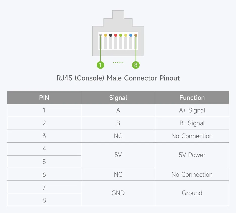
Different devices may have different RJ45 RS485 pin assignments. A standard straight-through cable only ensures pin-to-pin continuity; it does not guarantee signal compatibility with the peer device. Consult the peer device manual before connecting; do not connect to an Ethernet port.
Connecting to RS485 Devices
Use an RJ45 adapter board or make a custom cable according to the peer device's pinout, and connect the following signals:
| USB TO RS485 (D) | Target RS485 Device |
|---|---|
| A | A / D+ / 485+ |
| B | B / D- / 485- |
| GND | GND, connect according to site grounding scheme |
The 5 V auxiliary power on pins 4 and 5 should only be connected if the peer device's voltage and power requirements are confirmed to match, and the load current must not exceed 100 mA. If the peer does not require power, leave these two pins disconnected. Different devices may label RS485 A/B in reverse; if communication fails after correct wiring, refer to the peer device manual to verify polarity.
Termination Resistor Configuration
The product includes an onboard 120 Ω termination resistor switch. RS485 buses typically enable termination matching only at both ends of the trunk line, while intermediate nodes keep it disabled. For short-distance, low-baud-rate communication, termination resistors are generally not required; for long-distance or high-speed communication where signal reflection occurs, enable them at both ends of the bus.
Bus start                         Intermediate node                         Bus end
[120 Ω: Enabled] ================= [120 Ω: Disabled] ================= [120 Ω: Enabled]
RS485 Communication Test
- Connect the target RS485 device according to RJ45 Wiring, verifying the A, B, and GND definitions.
- Connect the converter to the host and confirm the virtual serial port in the system.
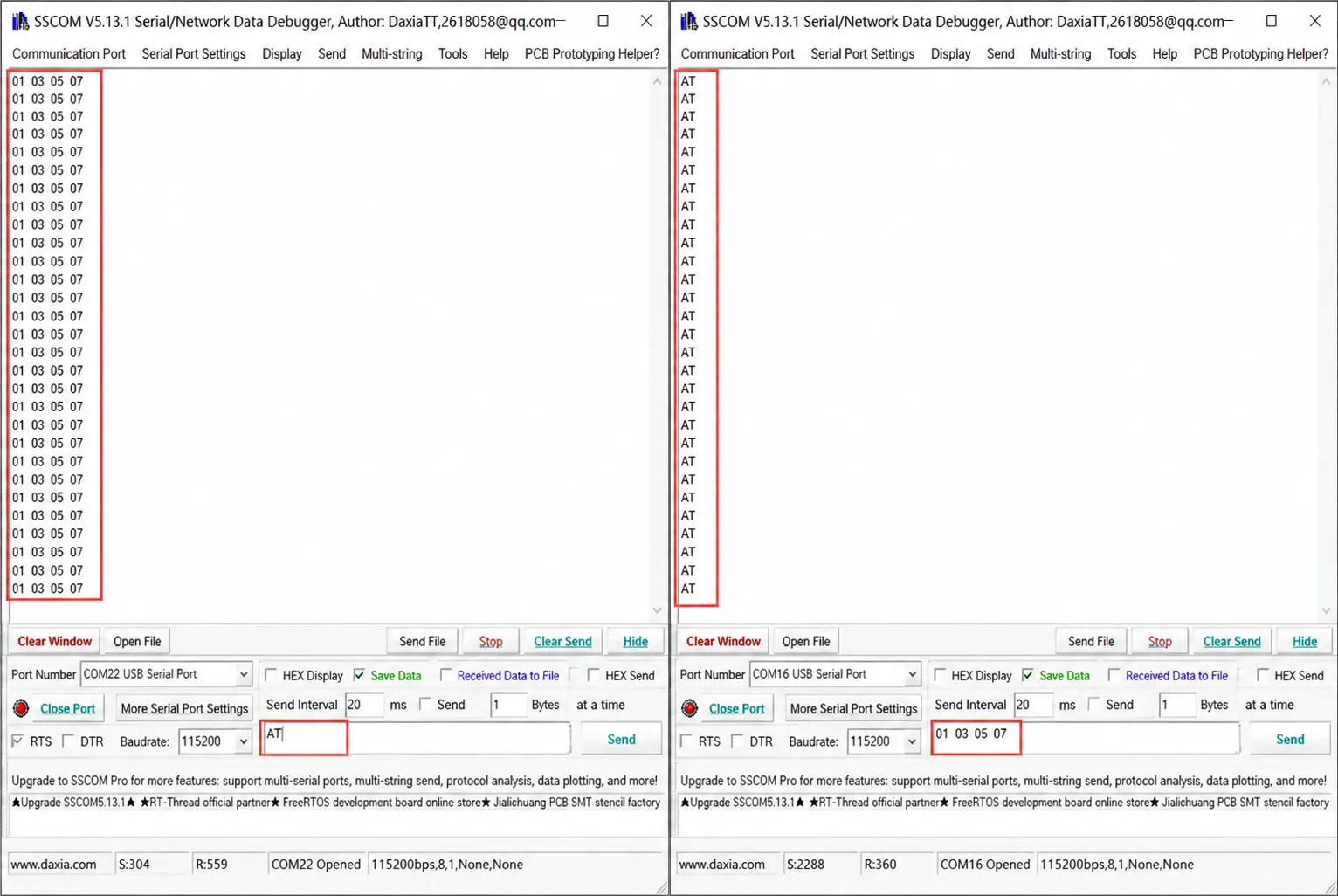
- Open a serial debug tool, select the corresponding COM port, and set the baud rate, data bits, parity, and stop bits to match the target device.
- Send test data and check the TXD, RXD indicators and the receive window.
- If communication fails, check A/B polarity, serial parameters, termination resistors, reference ground, and cable connections in sequence.
Modbus RTU Device Communication
USB TO RS485 (D) handles physical-layer conversion between USB and RS485 and does not include a built-in Modbus protocol stack. When connecting to Modbus RTU devices, the host software or master application must generate and parse Modbus frames.
- Confirm the slave address, baud rate, parity, data bits, and stop bits.
- Use a Modbus debugging tool or custom program to open the serial port corresponding to the converter.
- Set the function code, register address, and data format according to the slave device protocol manual.
- Send requests and check responses, indicators, and serial error messages.
Wiring Notes
- RS485 buses should use twisted-pair cables; shielded twisted-pair cables are recommended for long-distance or high-interference environments.
- For multi-node communication, use a bus topology and avoid long star branches.
- Isolation circuits do not replace on-site grounding, shielding, or lightning protection designs.
- When routing cables near high-voltage lines, variable-frequency drives, or motors, maintain appropriate spacing, shielding, and grounding per site specifications.