Section 06 Testing CAN Interface
TWAI is ESP32's official implementation of CAN Bus (Controller Area Network). It is a highly reliable, multi-master, real-time serial asynchronous communication protocol designed for automotive and industrial applications. It is essentially the CAN bus, with functionality, usage, and protocol identical to standard CAN. It is compatible with the frame structure defined in the ISO 11898-1 standard and supports both standard frames with 11-bit identifiers and extended frames with 29-bit identifiers.
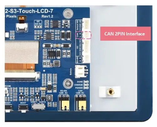
On this product, the ESP32-S3-Touch-LCD-7, we have brought out a PH2.0 2PIN connector that allows customers to connect to various CAN devices for communication and control.
For testing this CAN interface, we provide simple transmit and receive examples for communicating with a PC, making it easy for customers to quickly debug and test the interface.
Hardware Design
The ESP32 includes one TWAI controller peripheral, allowing the creation of a single driver instance. An external transceiver is required to connect to the TWAI bus. On this product, the ESP32-S3-Touch-LCD-7, we use GPIO19 and GPIO20 as the RX and TX pins respectively, connected to the onboard TJA1051T/3/1 transceiver, which converts to the CAN bus (CANH/CANL) communication interface. A simple circuit diagram is shown below:
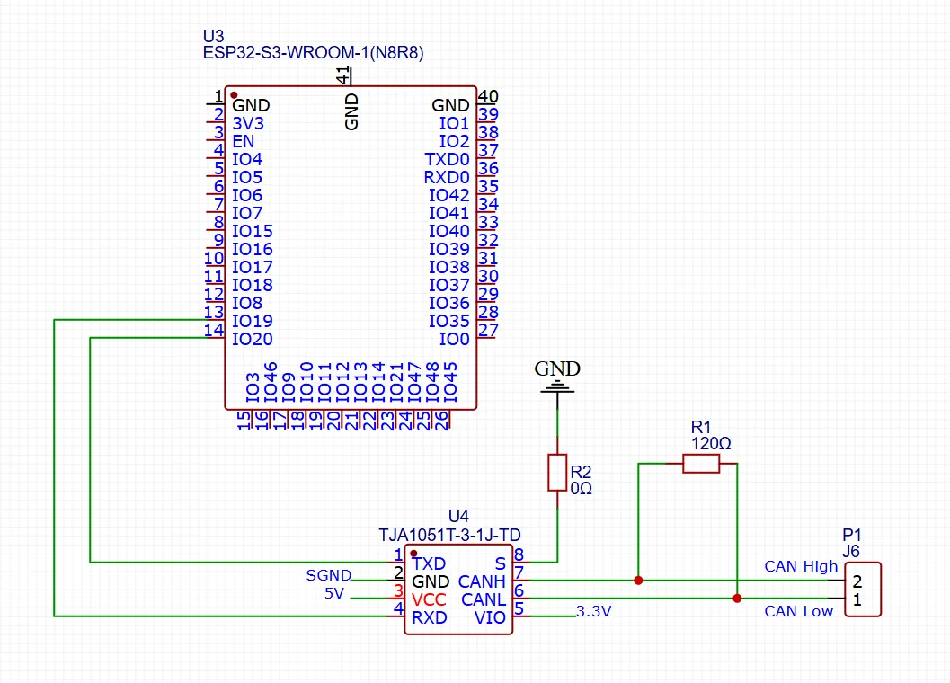
- A CAN node generally consists of three parts: microcontroller, CAN controller, and CAN transceiver. Some microcontrollers already include a CAN controller internally, e.g., the ESP32 has a built-in CAN (also called TWAI) controller; only an external CAN transceiver is needed for CAN communication. The transceiver is typically an 8PIN chip, such as the TJA1051T/3/1 used on our ESP32-S3-Touch-LCD-7.
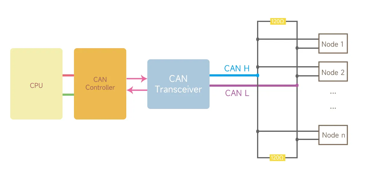
- All nodes are connected by two wires, called CAN_H and CAN_L. Both ends of the network must have a 120Ω termination resistor because the characteristic impedance of the cable is 120Ω. To simulate an infinite transmission line, a 120Ω resistor must be present on the circuit board, and a jumper or DIP switch selects whether to use this resistor.
Required Components
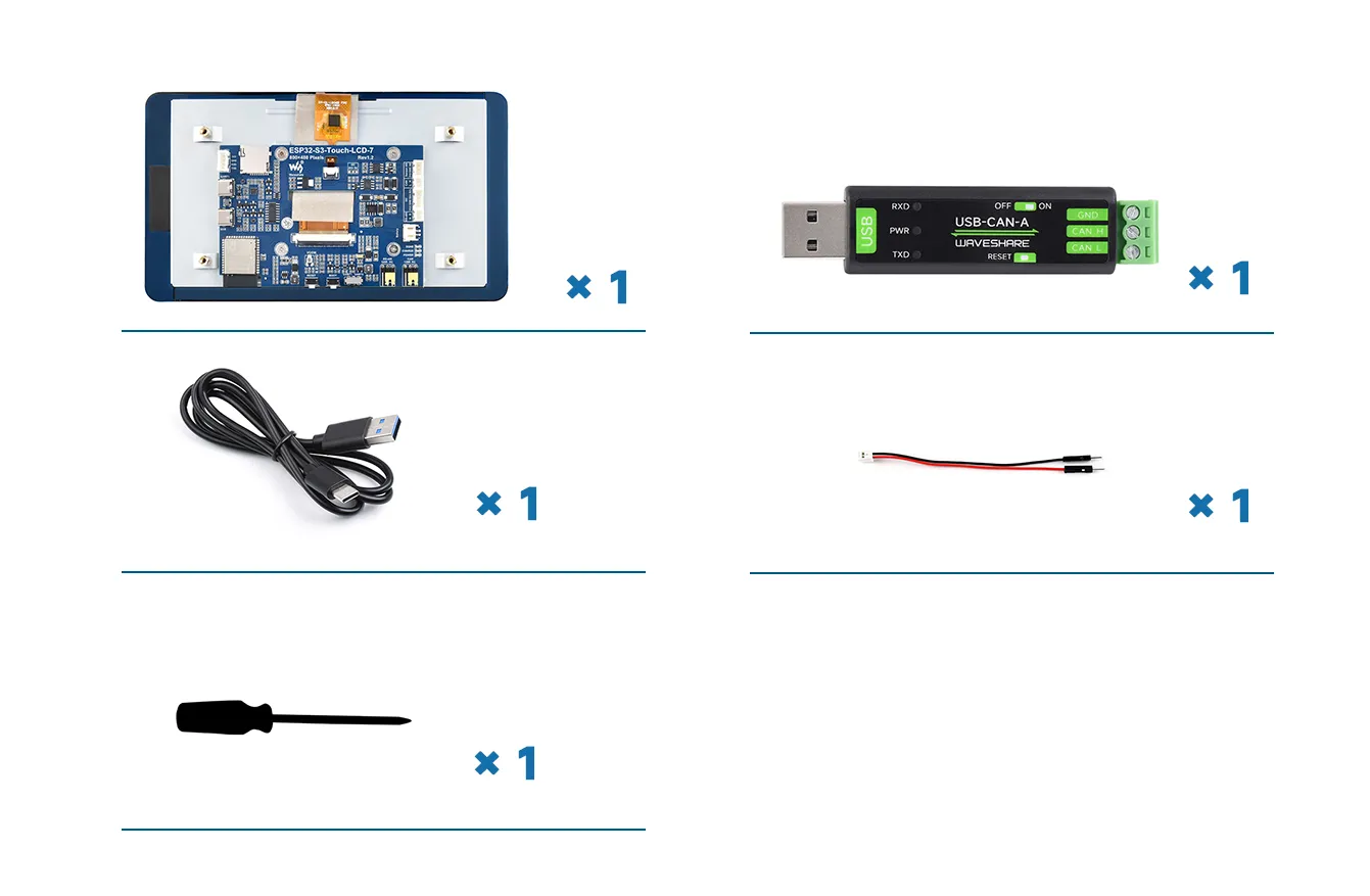
The components required for this example are:
- ESP32-S3-Touch-LCD-7 x1
- USB-CAN-A module x1
- USB cable Type-A male to Type-C male x1
- HY2.0 2PIN to male cable x1
- Flathead screwdriver x1
Hardware Connection
-
First connect the supplied 2PIN male cable connector to the white RS485 interface, ensuring good contact between the wire and the connector.
-
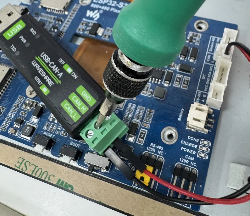
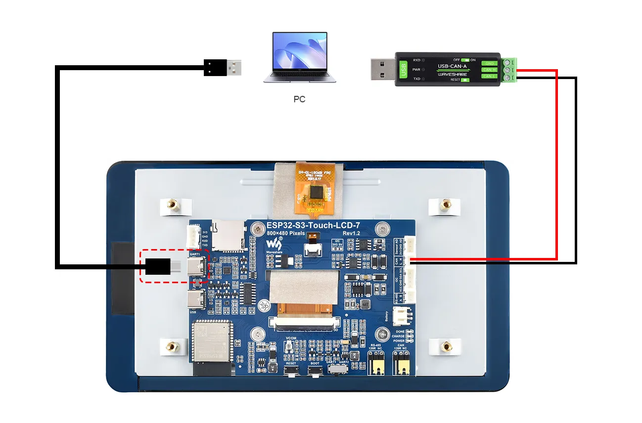
Connect the CAN H terminal of the ESP32-S3-Touch-LCD-7 to the CAN_H terminal of the USB-CAN-A module; similarly, connect the L terminal to CAN_L. Use a flathead screwdriver to adjust the screws on the USB-CAN-A module's connector, clamping the pins of the black and red wires to ensure a firm and stable connection.
-
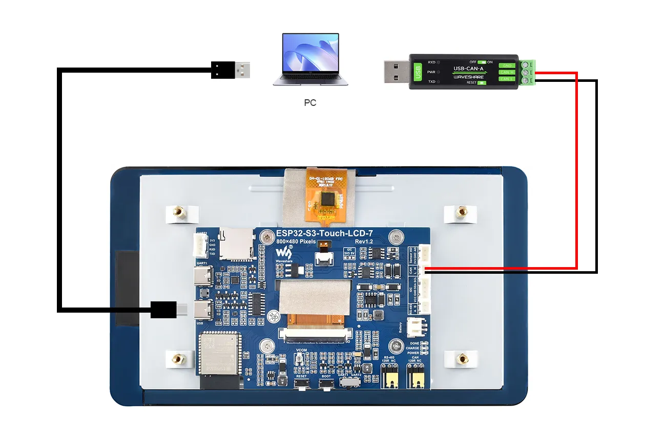
Then plug the USB port of the USB-CAN-A into the computer's USB port.
-
Use a Type-A male to Type-C USB cable to also connect the USB port of the ESP32 to the computer for downloading the program.
The complete connection is shown below:
CAN Transmit Example
Example
Please download the example package from the following address: ESP32-S3-Touch-LCD-7 Example (if already downloaded, simply open the corresponding folder).
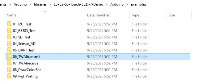
After extracting the example package, open the \Arduino\examples\06_TWAItransmit folder.
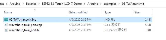
Double-click to open 06_TWAItransmit.ino
We have already connected the USB port for downloading the program. After opening the program, select the correct serial port and board model "Waveshare ESP32-S3-Touch-LCD-7" in the upper right corner.
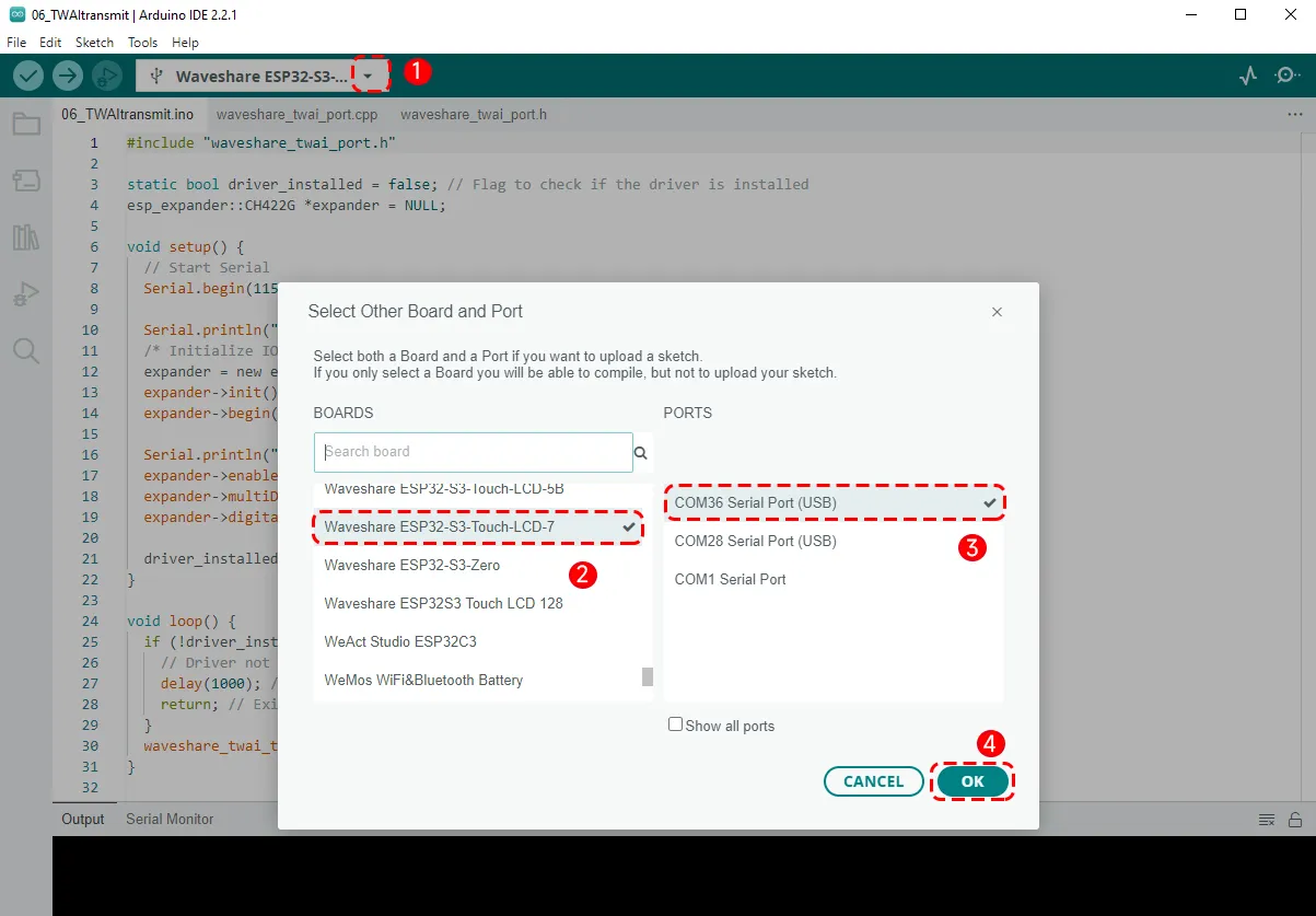
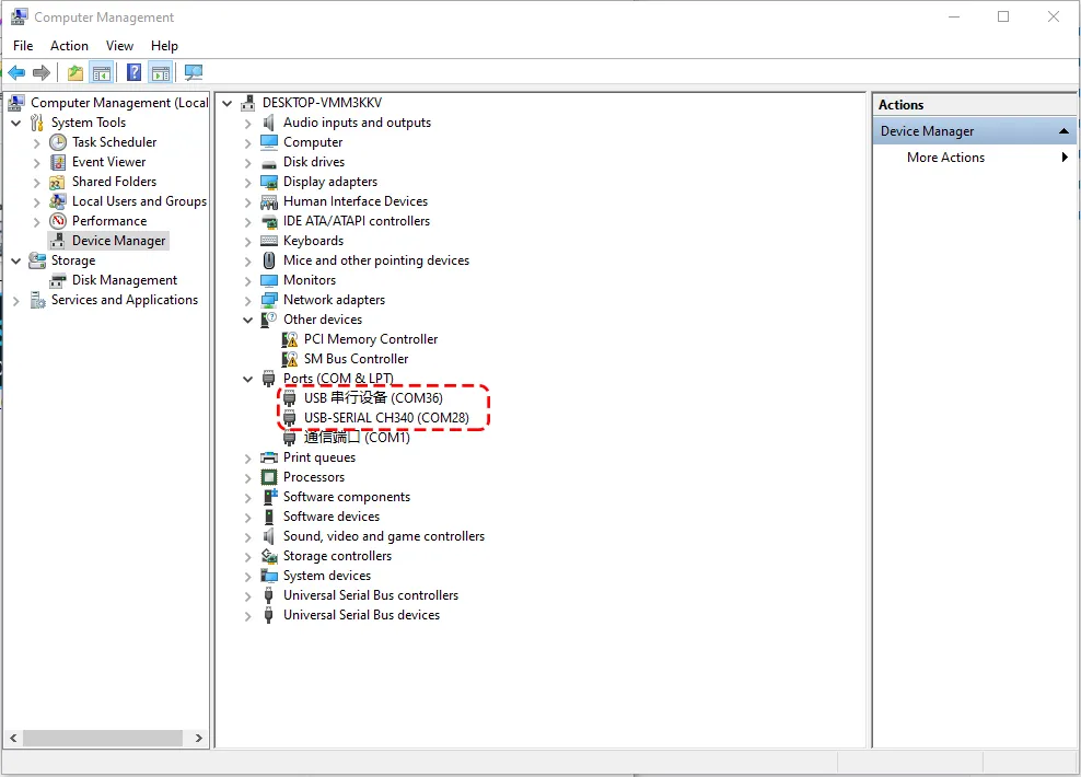
- Since the computer is now connected to both the ESP32-S3-Touch-LCD-7 and the USB-CAN-A module, two serial ports will be recognised. Open the computer's Device Manager: the one labelled "USB Serial Device" corresponds to the download interface, and the other is the CAN-to-USB serial port. When selecting the board, choose the COM port corresponding to the USB Serial Device:
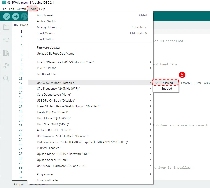
Note that in the Tools menu, "USB CDC On Boot" must be set to "Disabled". After the program runs, the USB port will no longer be usable (it shares GPIO19 and GPIO20 with the CAN interface; during CAN operation the USB port is disabled). The debug output of our program will be sent through the UART port:
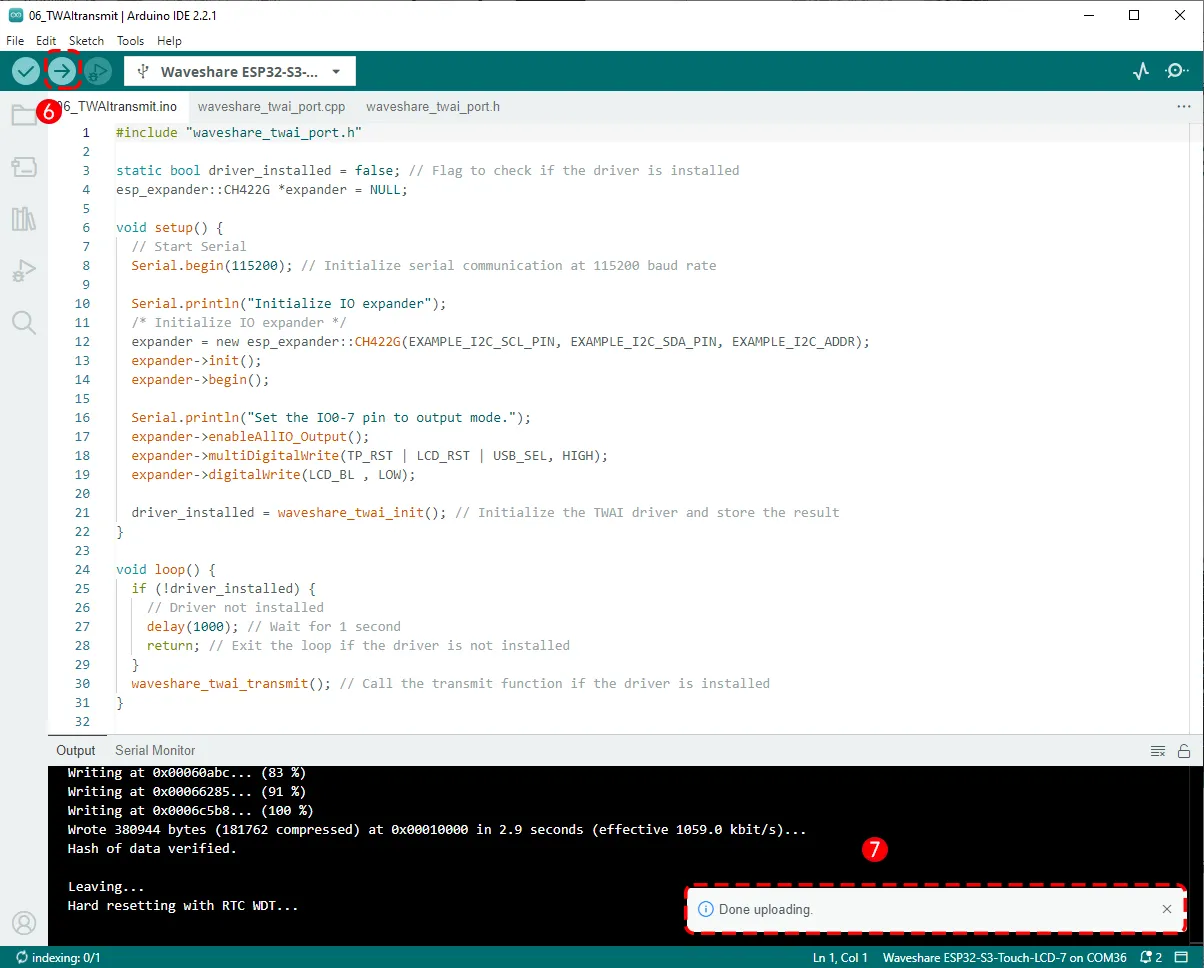
Then click the Upload button to upload the program, and wait for the upload to complete:
Running Results
After the download is complete, unplug the cable from the USB port of the ESP32-S3-Touch-LCD-7 and connect it to the UART port instead:
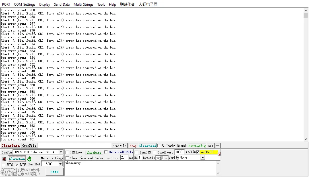
Now open the serial debugger sscom, select the port "USB-Enhanced-SERIAL CH343", open the port, and you will see debug output from the serial port. However, because the CAN communication has not yet started, bus error messages are printed:
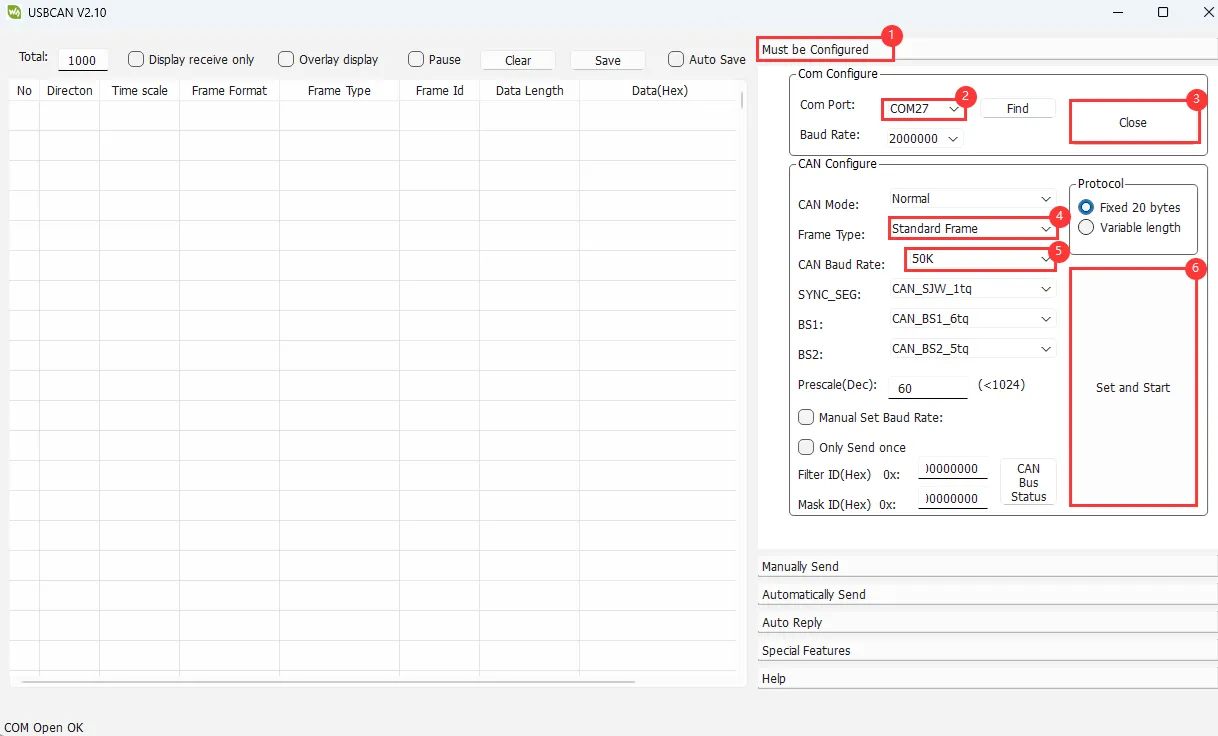
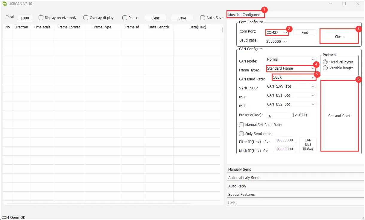
Now we start configuring the USB-CAN-A_TOOL software. Follow the steps to set it up.
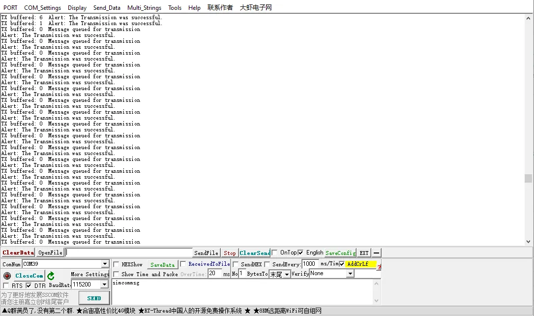
After a successful communication connection, you will see the debug print from the ESP32 on sscom: "The transmission was successful"
Meanwhile, the USB CAN tool also displays the CAN messages sent by the ESP32-S3-Touch-LCD-7:
The frame ID and data match what was configured in our program.
Code Review
We provide the CAN transmit example TWAItransmit.ino, along with the required header file waveshare_twai_port.h and source file waveshare_twai_port.cpp.
1. In waveshare_twai_port.h, the pins and parameters related to the TWAI (CAN bus) driver and some peripheral expansion pins are defined:
    #define RX_PIN 19
    #define TX_PIN 20
Defines GPIO19 of the ESP32-S3 for TWAI (CAN) reception, and GPIO20 for TWAI (CAN) transmission.
    #define TP_RST 1
    #define LCD_BL 2
    #define LCD_RST 3
    #define SD_CS 4
    #define USB_SEL 5
This part, similar to the previous TF card example, defines CH422G's GPIOs 1-5 for controlling multiple peripherals such as the LCD and TF card.
    #define EXAMPLE_I2C_ADDR (ESP_IO_EXPANDER_I2C_CH422G_ADDRESS)
    #define EXAMPLE_I2C_SDA_PIN 8         // I2C data line pins
    #define EXAMPLE_I2C_SCL_PIN 9         // I2C clock line pin
Defines the I2C address and pins of the CH422G expansion chip.
    #define TRANSMIT_RATE_MS 1000
    #define POLLING_RATE_MS 1000
Defines timing parameters: the TWAI message transmission interval (1000ms) and the polling period (every 1000ms). The polling period is used to set the wait time for reading alert events.
    bool waveshare_twai_init();
    void waveshare_twai_transmit();
Declarations of two TWAI functions, implemented in waveshare_twai_port.cpp, which will be explained below.
2. Implementation of functions inwaveshare_twai_port.cpp
unsigned long previousMillis = 0;
A timer variable previousMillis used with millis() to determine whether it is time to send (the send interval TRANSMIT_RATE_MS is set to 1000ms in the header file).
static void send_message() function: constructs and sends a TWAI message.
    twai_message_t message;
    message.identifier = 0x0F6; // Set message identifier
    message.data_length_code = 8; // Set data length
    for (int i = 0; i < message.data_length_code; i++) {
      message.data[i] = i; // Populate message data
    }
Builds a message structure: message.identifier sets the TWAI ID to 0x0F6(arbitration field, 11-bit standard frame); data_length_code sets the data length to 8 bytes, then fills the data with values 0 to 7. When we run this transmit program, it will send these eight bytes in one frame.
    if (twai_transmit(&message, pdMS_TO_TICKS(1000)) == ESP_OK) {
      printf("Message queued for transmission\n"); // Print success message
    }else{
      printf("Failed to queue message for transmission\n"); // Print failure message
    }
Attempts to send this frame and prints the corresponding serial information. If successful, prints "Message queued for transmission"; if the queue is full, the driver is not started, or the bus has an error, it fails and prints "Failed to queue message for transmission".
pdMS_TO_TICKS(1000) means it waits up to 1000ms; if the TX queue is full, it waits for 1 second and still fails, then returns failure.
memset(message.data, 0, sizeof(message.data));
Clears the entire data[8] array to prevent old data from being used next time.
waveshare_twai_init() function: initializes TWAI communication.
    twai_general_config_t g_config = TWAI_GENERAL_CONFIG_DEFAULT((gpio_num_t)TX_PIN, (gpio_num_t)RX_PIN, TWAI_MODE_NORMAL);
    twai_timing_config_t t_config = TWAI_TIMING_CONFIG_50KBITS();  // Set 50Kbps
    twai_filter_config_t f_config = TWAI_FILTER_CONFIG_ACCEPT_ALL(); // Accept all messages

    // Install TWAI driver
    if (twai_driver_install(&g_config, &t_config, &f_config) != ESP_OK) {
        Serial.println("Failed to install driver"); // Print error message
        return false; // Return false if driver installation fails
    }
    Serial.println("Driver installed"); // Print success message
- TWAI initialisation starts with driver installation using
twai_driver_installand three configuration structures:g_config,t_config, andf_config. - If
twai_driver_install()returnsESP_OK, the driver was installed successfully; the serial prints"Driver installed". Otherwise, it returnsfalseand prints"Failed to install driver".
- g_config: points to a general configuration structure (mode, GPIO pins, etc.). It is defined as:
    typedef struct {
    twai_mode_t mode;              // Operating mode (normal/listen-only/loopback)
    gpio_num_t tx_io_num;          // TX pin
    gpio_num_t rx_io_num;          // RX pin
    twai_clk_src_t clk_src;        // Clock source (APB or external)
    uint32_t alerts_enabled;       // Enabled alert flags
    twai_intr_flags_t intr_flags;  // Interrupt configuration
    } twai_general_config_t;
g_config = TWAI_GENERAL_CONFIG_DEFAULT((gpio_num_t)TX_PIN, (gpio_num_t)RX_PIN, TWAI_MODE_NORMAL); Here we set TX to GPIO20, RX to GPIO19, and the operating mode to normal mode.
-
t_config: points to a timing configuration structure (baud rate, clock divider, etc.). Here
t_config = TWAI_TIMING_CONFIG_50KBITS()sets the speed to 50 kbps. Common speeds also include 125 kbps, 250 kbps, 500 kbps. -
f_config: points to a filter configuration structure (receive filtering rules). Here
f_config = TWAI_FILTER_CONFIG_ACCEPT_ALL(); means accept all frames.
  if (twai_start() != ESP_OK) {
        Serial.println("Failed to start driver"); // Print error message
        return false; // Return false if starting the driver fails
    }
    Serial.println("Driver started"); // Print success message
The twai_start() function starts the TWAI controller. Returning ESP_OK indicates success; the serial prints "Driver started". If start fails, it returns false and prints "Failed to start driver".
    uint32_t alerts_to_enable = TWAI_ALERT_TX_IDLE | TWAI_ALERT_TX_SUCCESS | TWAI_ALERT_TX_FAILED | TWAI_ALERT_ERR_PASS | TWAI_ALERT_BUS_ERROR;
    if (twai_reconfigure_alerts(alerts_to_enable, NULL) != ESP_OK) {
        Serial.println("Failed to reconfigure alerts"); // Print error message
        return false; // Return false if alert reconfiguration fails
    }
    Serial.println("CAN Alerts reconfigured"); // Print success message
Here we enable listening for the following five events:
TWAI_ALERT_TX_IDLE: TX idleTWAI_ALERT_TX_SUCCESS: TX successTWAI_ALERT_TX_FAILED: TX failureTWAI_ALERT_ERR_PASS: Controller enters Error PassiveTWAI_ALERT_BUS_ERROR: Bus error occurred
These event macros are defined in the driver /twai_types_legacy.h header file. We combine multiple events into a single 32-bit integer alerts_to_enable using bitwise OR, then enable listening for these events with twai_reconfigure_alerts(). On success, it prints "CAN Alerts reconfigured".
At this point all initialization is complete and the function returns ture to the main program.
waveshare_twai_transmit() function:
    uint32_t alerts_triggered;
    twai_read_alerts(&alerts_triggered, pdMS_TO_TICKS(POLLING_RATE_MS)); // Read triggered alerts
    twai_status_info_t twaistatus; // Create status info structure
    twai_get_status_info(&twaistatus); // Get status information
twai_read_alerts() reads TWAI events that have occurred and writes the triggered events into alerts_triggered. pdMS_TO_TICKS(POLLING_RATE_MS) sets the blocking wait time; we set it to 1000 in the waveshare_twai_port.h header file, meaning it waits at most 1000ms. If a TWAI bus event occurs within 1000ms, it returns the event.
twai_status_info_t twaistatus creates a new structure to hold TWAI bus status information. twai_get_status_info() retrieves the current statistics (error counts, TX queue status). It contains many fields, such as:
- bus_error_count: number of bus errors
- tx_error_counter: transmit error counter
- msgs_to_tx: number of messages waiting to be sent
- tx_failed_count: number of failed transmissions
    if (alerts_triggered & TWAI_ALERT_ERR_PASS) {
      Serial.println("Alert: TWAI controller has become error passive."); // Print passive error alert
    }
    if (alerts_triggered & TWAI_ALERT_BUS_ERROR) {
      Serial.println("Alert: A (Bit, Stuff, CRC, Form, ACK) error has occurred on the bus."); // Print bus error alert
      Serial.printf("Bus error count: %d\n", twaistatus.bus_error_count); // Print bus error count
    }
    if (alerts_triggered & TWAI_ALERT_TX_FAILED) {
      Serial.println("Alert: The Transmission failed."); // Print transmission failure alert
      Serial.printf("TX buffered: %d\t", twaistatus.msgs_to_tx); // Print buffered TX messages
      Serial.printf("TX error: %d\t", twaistatus.tx_error_counter); // Print TX error count
      Serial.printf("TX failed: %d\n", twaistatus.tx_failed_count); // Print failed TX count
    }
    if (alerts_triggered & TWAI_ALERT_TX_SUCCESS) {
      Serial.println("Alert: The Transmission was successful."); // Print successful transmission alert
      Serial.printf("TX buffered: %d\t", twaistatus.msgs_to_tx); // Print buffered TX messages
    }
Checks which alert events have occurred and handles them accordingly.
TWAI_ALERT_ERR_PASSError passive state: when the TWAI controller's TX error counter ≥ 128 or RX error counter ≥ 128, it enters Error Passive. The controller may have serious communication errors but is not yet completely offline.TWAI_ALERT_BUS_ERRORBus error: triggered when any of the following protocol-level errors occur on the TWAI bus: Bit Error, Stuff Error, CRC Error, Form Error, ACK Error. The receive counter will increase.TWAI_ALERT_TX_FAILEDTransmission failed: triggered when arbitration fails or ACK write fails, preventing the entire frame from being transmitted. This means the TWAI frame was not sent successfully and requires retransmission; relevant statistics are printed.TWAI_ALERT_TX_SUCCESSTransmission successful: the TWAI controller successfully sent a CAN frame onto the bus and received at least one ACK.
    unsigned long currentMillis = millis(); // Get current time in milliseconds
    if (currentMillis - previousMillis >= TRANSMIT_RATE_MS) { // Check if it's time to send a message
      previousMillis = currentMillis; // Update last send time
      send_message(); // Call function to send message
    }
In the header file waveshare_twai_port.h, TRANSMIT_RATE_MS was set to 1000ms. This code sets the transmission to occur every 1000ms.
3. Main Program TWAItransmit.ino
#include "waveshare_twai_port.h"
Includes the header file waveshare_twai_port.
    static bool driver_installed = false; // Flag to check if the driver is installed
    esp_expander::CH422G *expander = NULL;
A boolean driver_installed stores the result of TWAI driver installation. esp_expander::CH422G *expander = NULL defines a pointer to a CH422G object, which will be dynamically created later with new.
void setup() function:
    Serial.begin(115200); // Initialize serial communication at 115200 baud rate
    Serial.println("Initialize IO expander");
Initializes the serial port with baud rate 115200 for printing debug information.
    expander = new esp_expander::CH422G(EXAMPLE_I2C_SCL_PIN, EXAMPLE_I2C_SDA_PIN, EXAMPLE_I2C_ADDR);
    expander->init();
    expander->begin();
Creates a new CH422G object, specifying the I2C clock line (SCL), data line (SDA), and I2C address, then calls init() and begin() to complete initialisation.
    Serial.println("Set the IO0-7 pin to output mode.");
    expander->enableAllIO_Output();
    expander->multiDigitalWrite(TP_RST | LCD_RST | USB_SEL, HIGH);
    expander->digitalWrite(LCD_BL , LOW);
Sets all expansion I/O pins as outputs and configures their states. Setting USB_SEL = HIGH enables the FSUSB42UMX chip, so GPIO19/20 are used as CAN_TX/CAN_RX.
driver_installed = waveshare_twai_init();
Initializes the TWAI communication interface and stores the result in driver_installed.
    void loop() {
      if (!driver_installed) {
        // Driver not installed
        delay(1000); // Wait for 1 second
        return; // Exit the loop if the driver is not installed
      }
      waveshare_twai_transmit(); // Call the transmit function if the driver is installed
    }
The void loop() function first checks whether driver_installed is successful. If initialization fails, it exits the loop; if successful, it starts the waveshare_twai_transmit() program, which:
- Checks for alerts (transmission success/failure, bus errors)
- Sends a CAN message periodically every
TRANSMIT_RATE_MS - Prints logs and automatically handles status information
CAN Receive Example
In the previous tutorial we tried how to send using the CAN interface. Now let's try how to receive using the CAN interface.
Example
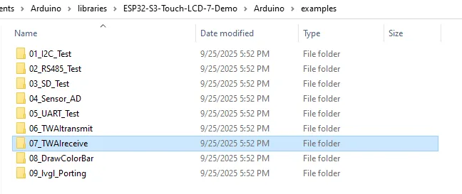
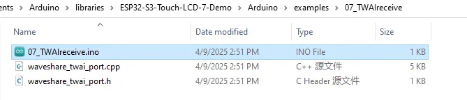
Open the corresponding \Arduino\examples\07_TWAIreceive folder:
Double-click to open 07_TWAIreceive.ino:
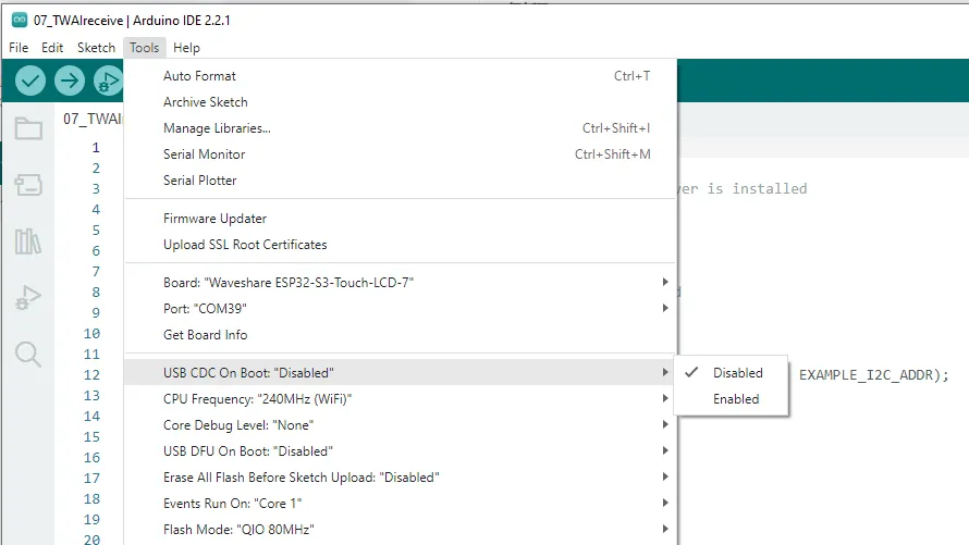
As before, select the correct serial port and board model "Waveshare ESP32-S3-Touch-LCD-7" in the upper right corner, set the download configuration: "USB CDC On Boot" to "Disabled", then click the flash button to download the program.
Running Results
After flashing, unplug the cable from the USB port of the ESP32-S3-Touch-LCD-7 and connect it to the UART port, and also connect the CAN interface to the computer via the USB-to-CAN module.
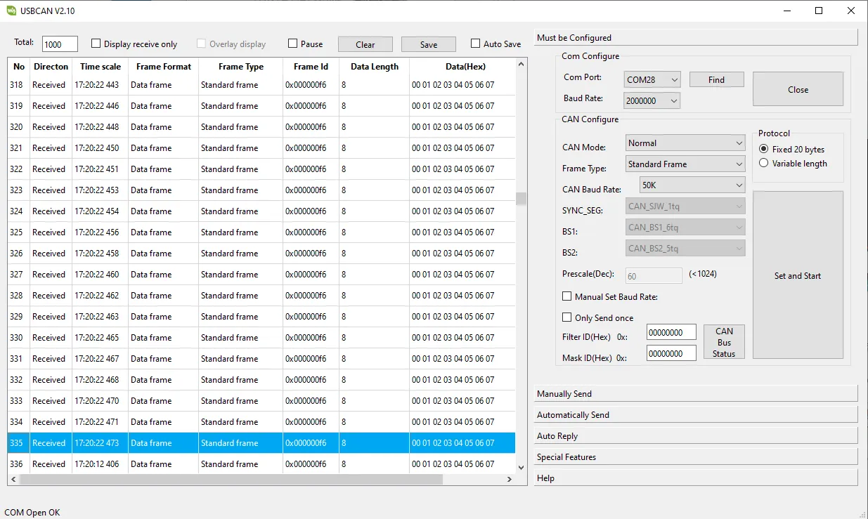
Configure the USB-CAN-A_TOOL parameters as shown. Note that the CAN speed is 500K:
Click "Manually Send" and randomly send data with any ID:
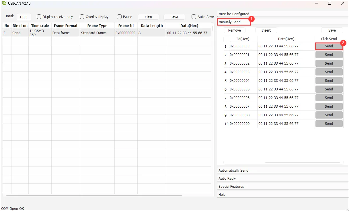
Then you will see the serial output from the ESP32, displaying the data type, device ID, and the 8 bytes of data.
Code Review
We provide the CAN receive example TWAIreceive.ino, along with the required header file waveshare_twai_port.h and source file waveshare_twai_port.cpp.
The structure of TWAIreceive.ino and waveshare_twai_port.h is very similar to the previous transmit example, so we will not repeat that explanation. Instead, we focus on the handle_rx_message() and waveshare_twai_receive() functions in waveshare_twai_port.cpp.
handle_rx_message() function: processes received messages:
static void handle_rx_message(twai_message_t &message)
twai_message_t &message: a reference to a TWAI message structure, allowing direct modification of the original message without copying.
    if (message.extd)
    {
      Serial.println("Message is in Extended Format"); // Print if the message is in extended format
    }
    else
    {
      Serial.println("Message is in Standard Format"); // Print if the message is in standard format
    }
    Serial.printf("ID: %x\nByte:", message.identifier); // Print message ID
Message.extd checks whether the message is in extended format or standard format and prints accordingly. Serial.printf("ID: %x\nByte:", message.identifier); prints the ID of the sending device; %x outputs in hexadecimal.
    if (!(message.rtr))
      { // Check if it is not a remote transmission request
        for (int i = 0; i < message.data_length_code; i++)
        {
          Serial.printf(" %d = %02x,", i, message.data[i]); // Print each byte of the message data
        }
        Serial.println(""); // Print a new line
      }
message.rtr checks whether it is a remote transmission request frame. The ! negation means that if it is not a remote frame (i.e., it is a data frame), the following code executes: loop over all data bytes and print each byte's value in two-digit hexadecimal.
Serial.println(""); // Print a new line
Prints a newline to make output clearer.
waveshare_twai_receive() function:
    uint32_t alerts_triggered;
    twai_read_alerts(&alerts_triggered, pdMS_TO_TICKS(POLLING_RATE_MS)); // Read triggered alerts
    twai_status_info_t twaistatus; // Create status info structure
    twai_get_status_info(&twaistatus); // Get status information
Like the transmit program, this reads TWAI events that have occurred and saves TWAI bus status information.
    if (alerts_triggered & TWAI_ALERT_ERR_PASS)
    {
      Serial.println("Alert: TWAI controller has become error passive."); // Print passive error alert
    }
    if (alerts_triggered & TWAI_ALERT_BUS_ERROR)
    {
      Serial.println("Alert: A (Bit, Stuff, CRC, Form, ACK) error has occurred on the bus."); // Print bus error alert
      Serial.printf("Bus error count: %d\n", twaistatus.bus_error_count); // Print bus error count
    }
Checks whether error-passive or bus-error events have occurred.
    if (alerts_triggered & TWAI_ALERT_RX_QUEUE_FULL)
    {
      Serial.println("Alert: The RX queue is full causing a received frame to be lost."); // Print RX queue full alert
      Serial.printf("RX buffered: %d\t", twaistatus.msgs_to_rx);                          // Print buffered RX messages
      Serial.printf("RX missed: %d\t", twaistatus.rx_missed_count);                       // Print missed RX count
      Serial.printf("RX overrun %d\n", twaistatus.rx_overrun_count);                      // Print RX overrun count
    }
Checks whether the receive queue is full and frames have been lost. If so, it prints:
RX buffered: number of messages still in the queue that have not been readRX missed: number of frames dropped because the queue was fullRX overrun: number of receive overflows This usually happens because the code is not reading fast enough or the sender's transmission frequency is too high for the ESP32's processing capability.
    if (alerts_triggered & TWAI_ALERT_RX_DATA)
    {
      // One or more messages received. Handle all.
      twai_message_t message;
      while (twai_receive(&message, 0) == ESP_OK)
      {                             // Receive messages
        handle_rx_message(message); // Handle each received message
      }
    }
First, if (alerts_triggered & TWAI_ALERT_RX_DATA) detects whether any data frames have been received. If so, it reads all received CAN messages from the RX queue one by one and hands them to handle_rx_message() for processing.
twai_message_t message is a message structure defined by the TWAI framework; each frame's data/ID/length/timestamp, etc., are stored here. A while loop reads all messages; the second parameter of twai_receive(&message, 0) is a timeout – 0 means no waiting. If there is no message, the while loop exits immediately.
handle_rx_message(message) is the previously explained function that processes received data: it determines the frame type, prints the TWAI ID, prints the data content, etc.