Section 01 Debugging I2C Interface
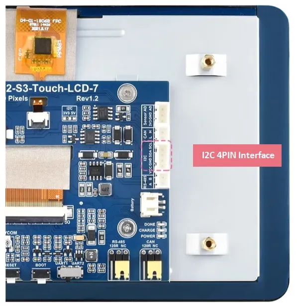
The ESP32-S3 chip has two I2C controllers, which can be configured as masters or slaves and can be mapped to most GPIO pins. On the ESP32-S3-Touch-LCD-7, we have brought out a PH2.0 4PIN connector connected to IO8 and IO9 of the ESP32-S3 chip, making it easy for customers to map these two pins as an I2C communication interface for connecting and debugging I2C devices.
To demonstrate the basic I2C driver method for the ESP32 in Arduino, we provide an I2C address scanning example to help users quickly understand the driver steps.
Hardware Connection
To upload the corresponding code to the ESP32-S3, you need to connect the USB port of the ESP32-S3-Touch-LCD-7 to the computer's USB port using a Type-C to Type-A cable.
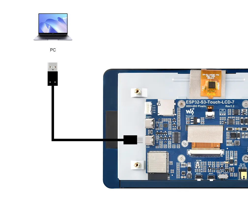
Please prepare a Type-C to Type-A USB data cable yourself. A charging-only USB cable will not work.
Example
Please download the example package from the following address: ESP32-S3-Touch-LCD-7 example (if already downloaded, simply open the corresponding folder).
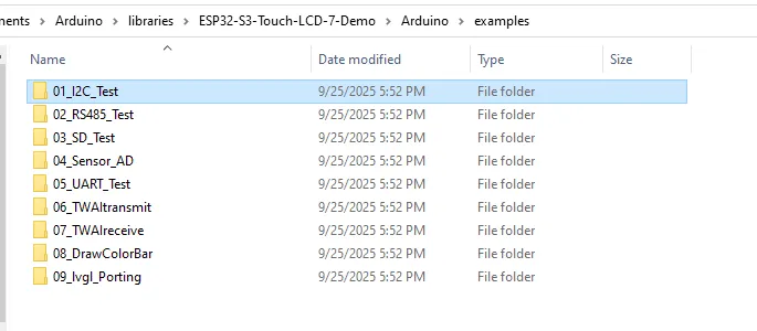
After extracting the example package, open the 01_I2C_Test folder:
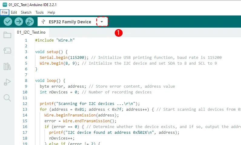
Double-click to open 01_I2C_Test.ino:

Before uploading the code to the ESP32, we need to select the correct COM port and board model. Click the small triangle next to the model name in the top left corner:
When the ESP32-S3 is connected to the computer, it normally identifies a COM port; for example, in my case it is COM36. Click "Select other board and port" at the bottom:
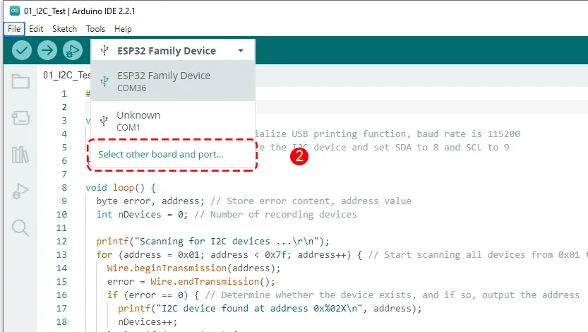
The first time the board is connected to the computer, the Arduino IDE will automatically recognize it as some default ESP32 model, such as "ESP32 Family Device" in the image above. This is normal; we will select the correct board model in the next step.
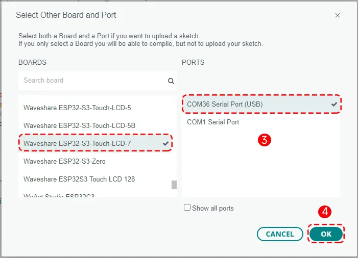
After clicking COM36, a window for selecting the board and port will pop up. Here we select the board model "Waveshare ESP32-S3-Touch-LCD-7", the port "COM36 Serial Port (USB)", and then click the OK button in the bottom right corner to confirm.
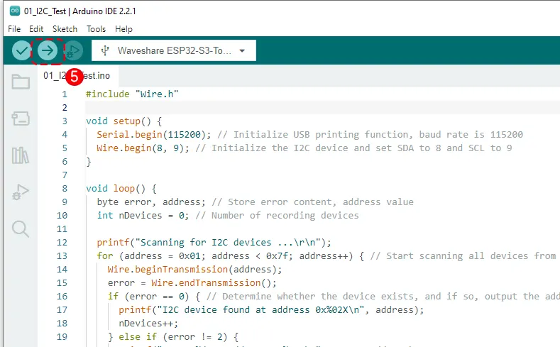
After setting, click the Upload button to upload.
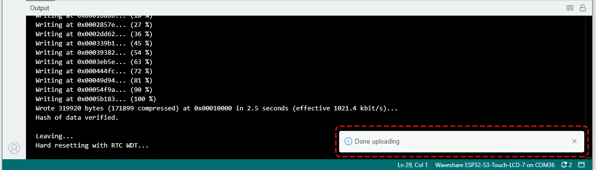
Wait for the program to compile and upload.
Running Results
After uploading the code, open the Serial Monitor from the Tools menu.
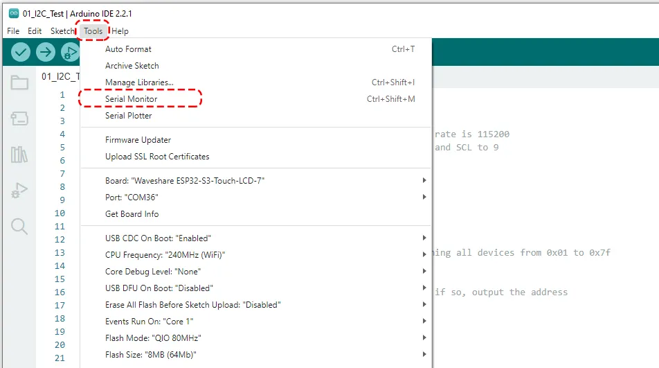
Set the appropriate baud rate (115200). After the program runs, the Serial Monitor will display "Scanning for I2C devices ..." followed by the addresses of any I2C devices found.
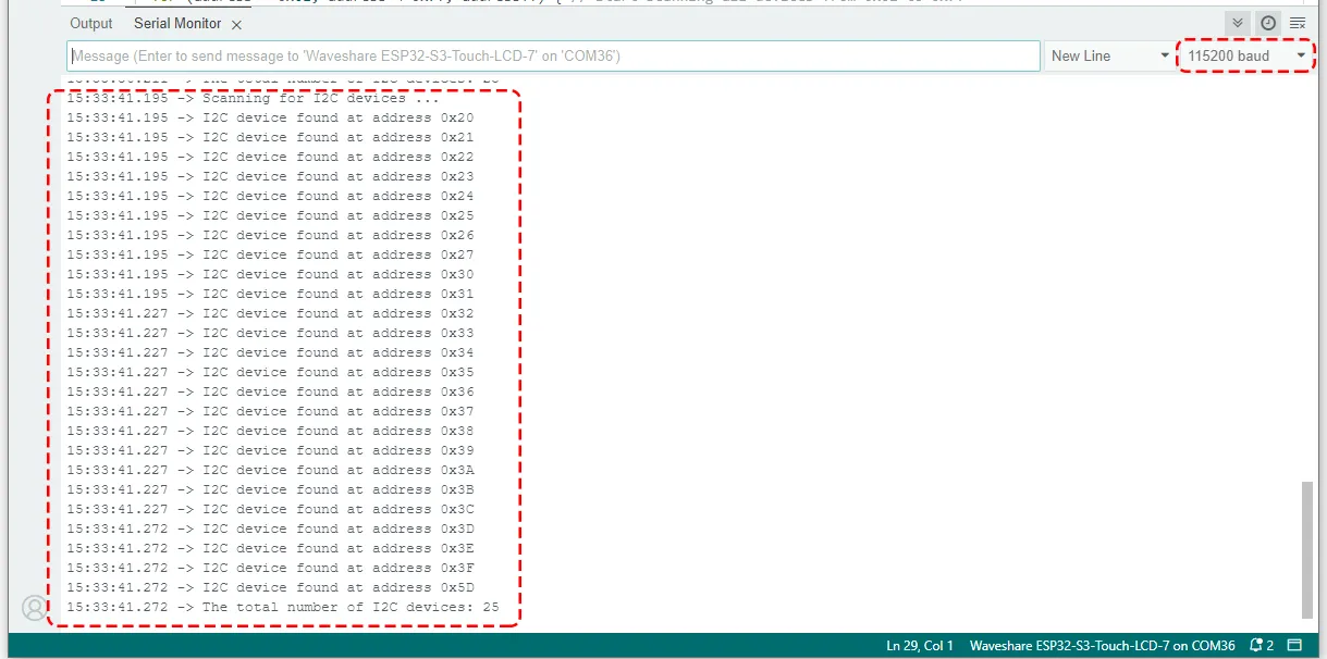
The program runs every 5 seconds, so the Serial Monitor will refresh continuously.
Code Review
    #include "Wire.h"

    void setup() {
      Serial.begin(115200); // Initialize USB printing function, baud rate is 115200
      Wire.begin(8, 9); // Initialize the I2C device and set SDA to 8 and SCL to 9
    }

    void loop() {
      byte error, address; // Store error content, address value
      int nDevices = 0; // Number of recording devices

      printf("Scanning for I2C devices ...\r\n");
      for (address = 0x01; address < 0x7f; address++) { // Start scanning all devices from 0x01 to 0x7f
        Wire.beginTransmission(address);
        error = Wire.endTransmission();
        if (error == 0) { // Determine whether the device exists, and if so, output the address
          printf("I2C device found at address 0x%02X\n", address);
          nDevices++;
        } else if (error != 2) {
          printf("Error %d at address 0x%02X\n", error, address);
        }
      }
      if (nDevices == 0) { // Determine the number of devices. If it is 0, there is no device.
        printf("No I2C devices found.\r\n");
      }
      delay(5000); // Scan every 5 seconds
    }
#include <Wire.h>: Introduces the Arduino I2C communication library.Wire.begin(SDA_PIN, SCL_PIN): Initializes the I2C bus as a master device. On the ESP32, the function has multiple forms:Wire.begin(): Does not specify a pin, uses the default I2C pin defined for the current development board, such as GPIO 21 (SDA) and GPIO 22 (SCL). The schematic or pin definition of the board used shall prevail.Wire.begin(SDA_PIN, SCL_PIN): Uses the specified GPIO pins as I2C pins. Here we define IO8 and IO9 as SDA and SCL respectively.
for (address = 0x01; address < 0x7f; address++): Loop through all possible 7-bit I2C addresses.Wire.beginTransmission(address): The ESP32 (master device) attempts to establish communication with the specifiedaddress.Wire.endTransmission(): Ends the communication attempt and returns a status code.0: Success, the slave device has responded (ACK).2: The slave device did not respond (NACK) when receiving the address. This is the most common case, indicating that there is no device at the address.3: The slave device did not respond (NACK) when receiving the data.4: Other errors.
Serial.printf("I2C device found at address 0x%02X\n", address);: If a device is found, its address is printed in hexadecimal format (e.g.,0x27or0x3C). AndnDevicesis incremented.Serial.printf("No I2C devices found.\r\n");: After scanning all I2C addresses, if the accumulated countnDevicesis 0, it prints that no I2C device was found.