docs Section 08 Porting LVGL
This section uses the LVGL v8 example from the example package. It drives the display and touch panel through the ESP32_Display_Panel library and displays an official LVGL example.
Hardware Connection
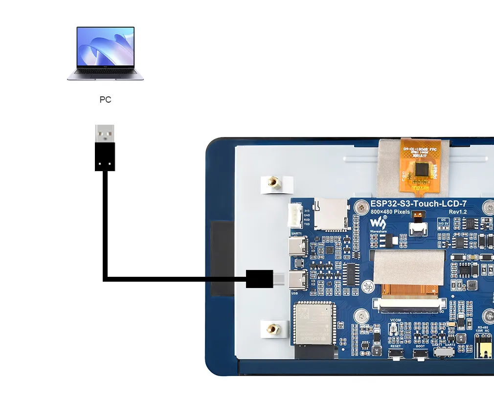
To upload the corresponding code to the ESP32-S3, you need to connect the USB port of the ESP32-S3-Touch-LCD-7 to the computer's USB port using a Type-C to Type-A cable:
Example
Please download the example package from the following address: ESP32-S3-Touch-LCD-7 Example (if already downloaded, simply open the corresponding folder).
After downloading or cloning the repository, open the corresponding examples/Arduino/examples/09_lvgl_v8_demo folder.
Double-click to open 09_lvgl_v8_demo.ino.
In the Arduino IDE, select the serial port and board model Waveshare ESP32-S3-Touch-LCD-7.
Set the corresponding board parameters:
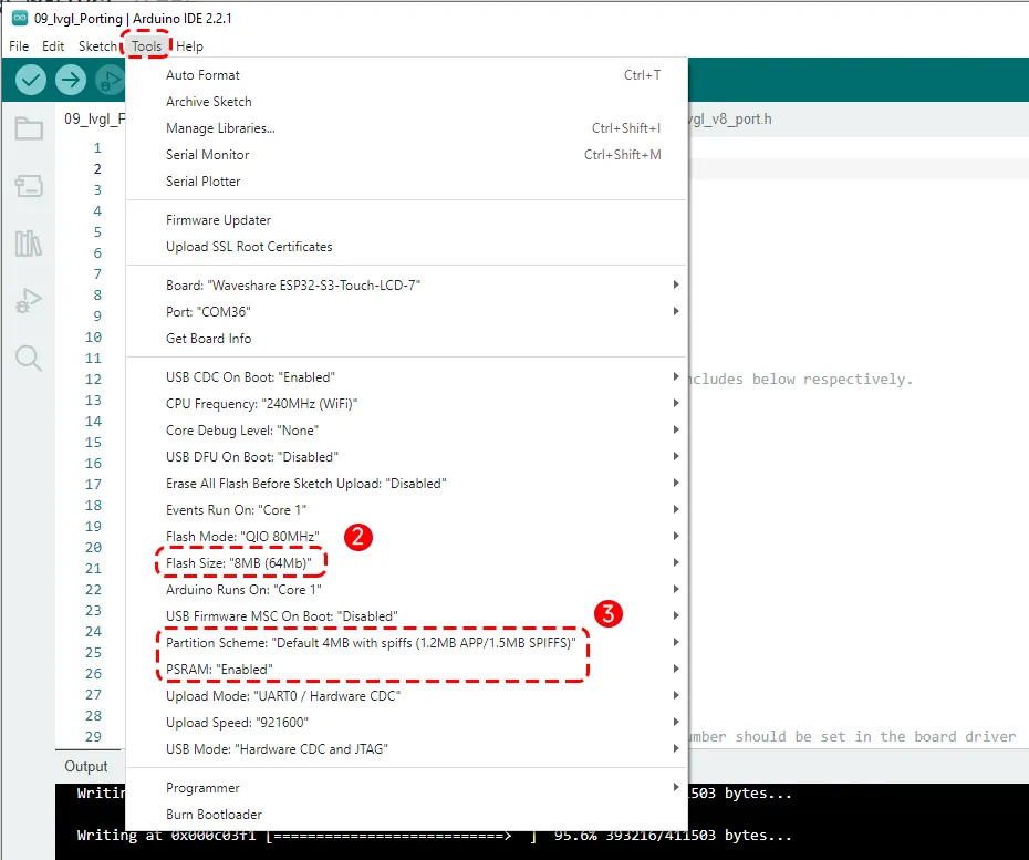
Then click the Upload button to upload the program, and wait for the upload to complete.
Running Results
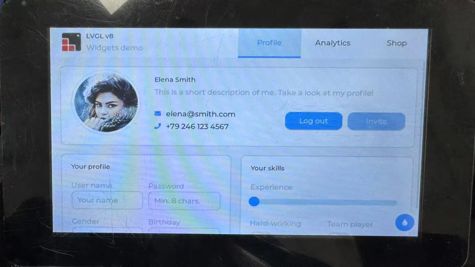
Power cycle the screen, and you will see the LVGL v8 example displayed on the screen. For the version with a touch panel, slide on the screen to test the touch function.
Code Review
1. Driving the Display and Touch Panel
This example uses the esp_panel_board_custom_conf.h file in the example directory to configure the display, touch panel, backlight, and I/O expander. For information about configuring this file, refer to the ESP32_Display_Panel official documentation.
The main configuration used by this example is described below.
Enable custom LCD panel
#define ESP_PANEL_BOARD_DEFAULT_USE_CUSTOM (1)
First, change the macro ESP_PANEL_BOARD_DEFAULT_USE_CUSTOM from 0 to 1 to enable custom configuration. This will enable the configuration parameters under #if ESP_PANEL_BOARD_DEFAULT_USE_CUSTOM.
    #define ESP_PANEL_BOARD_NAME                "Waveshare:ESP32-S3-Touch-LCD-7"
    #define ESP_PANEL_BOARD_WIDTH               (800)   // Panel width (horizontal, in pixels)
    #define ESP_PANEL_BOARD_HEIGHT              (480)   // Panel height (vertical, in pixels)
Set the custom board name and define the screen resolution.
Set LCD parameters
#define ESP_PANEL_BOARD_USE_LCD (1)
Change the macro ESP_PANEL_BOARD_USE_LCD from 0 to 1 to enable the LCD panel. This will enable the configuration parameters under #if ESP_PANEL_BOARD_USE_LCD.
    #define ESP_PANEL_BOARD_LCD_CONTROLLER      ST7262
    #define ESP_PANEL_BOARD_LCD_BUS_TYPE        (ESP_PANEL_BUS_TYPE_RGB)
Define the LCD controller IC and communication type - choose RGB bus communication.
    #if ESP_PANEL_BOARD_LCD_BUS_TYPE == ESP_PANEL_BUS_TYPE_RGB
    #define ESP_PANEL_BOARD_LCD_RGB_USE_CONTROL_PANEL       (0) // 0/1. Typically set to 1

        #define ESP_PANEL_BOARD_LCD_RGB_CLK_HZ          (16 * 1000 * 1000)
        ...
        #define ESP_PANEL_BOARD_LCD_RGB_IO_DATA15 (40)

    #endif
ESP_PANEL_BOARD_LCD_RGB_USE_CONTROL_PANEL is set to 0, indicating that an RGB interface without three-wire SPI is used. The remaining parameters are configured according to the LCD specifications, as in the previous RGB bar example.
Set touch panel parameters
#define ESP_OPEN_TOUCH 1
Define the macro to enable touch functionality. A value of 0 disables touch, 1 enables touch - choose according to the purchased model.
#define ESP_PANEL_BOARD_USE_TOUCH (ESP_OPEN_TOUCH)
Since we set ESP_OPEN_TOUCH to 1, the touch configuration under #if ESP_PANEL_BOARD_USE_TOUCH will be enabled. If you purchased the non-touch version, set ESP_OPEN_TOUCH to 0 to disable the touch panel parameters.
    #define ESP_PANEL_BOARD_TOUCH_CONTROLLER        GT911
    #define ESP_PANEL_BOARD_TOUCH_BUS_TYPE          (ESP_PANEL_BUS_TYPE_I2C)
Define the touch controller as GT911 and the communication interface as I2C bus.
    #define ESP_PANEL_BOARD_TOUCH_I2C_IO_SCL            (9)
    #define ESP_PANEL_BOARD_TOUCH_I2C_IO_SDA            (8)
    #define ESP_PANEL_BOARD_TOUCH_INT_IO                (4)
Here we set the SCL, SDA, and interrupt pins for the touch.
Set backlight parameters
#define ESP_PANEL_BOARD_USE_BACKLIGHT (1)
Set ESP_PANEL_BOARD_USE_BACKLIGHT to 1 to enable backlight control, which will enable the configuration under #if ESP_PANEL_BOARD_USE_BACKLIGHT.
    #define ESP_PANEL_BOARD_BACKLIGHT_TYPE          (ESP_PANEL_BACKLIGHT_TYPE_SWITCH_EXPANDER)

    #if (ESP_PANEL_BOARD_BACKLIGHT_TYPE == ESP_PANEL_BACKLIGHT_TYPE_SWITCH_GPIO) || \
        (ESP_PANEL_BOARD_BACKLIGHT_TYPE == ESP_PANEL_BACKLIGHT_TYPE_SWITCH_EXPANDER) || \
        (ESP_PANEL_BOARD_BACKLIGHT_TYPE == ESP_PANEL_BACKLIGHT_TYPE_PWM_LEDC)

        #define ESP_PANEL_BOARD_BACKLIGHT_IO        (2)    // Output GPIO pin number
        #define ESP_PANEL_BOARD_BACKLIGHT_ON_LEVEL  (1)     // Active level, 0: low, 1: high

    #endif
Here the backlight type is set to be controlled by an I/O expander, and the control I/O pin is set to EXIO2.
#define ESP_PANEL_BOARD_BACKLIGHT_IDLE_OFF (0)
Set the backlight to be on after initialization.
Set I/O expander parameters
#define ESP_PANEL_BOARD_USE_EXPANDER (1)
Set the macro ESP_PANEL_BOARD_USE_EXPANDER to 1 to enable the I/O expander, which will enable the configuration under #if ESP_PANEL_BOARD_USE_EXPANDER.
#define ESP_PANEL_BOARD_EXPANDER_CHIP CH422G
Set the I/O expander chip name to CH422G.
    #define ESP_PANEL_BOARD_EXPANDER_I2C_CLK_HZ         (400 * 1000)
                                                                // Typically set to 400K
    #define ESP_PANEL_BOARD_EXPANDER_I2C_SCL_PULLUP     (1)     // 0/1. Typically set to 1
    #define ESP_PANEL_BOARD_EXPANDER_I2C_SDA_PULLUP     (1)     // 0/1. Typically set to 1
    #define ESP_PANEL_BOARD_EXPANDER_I2C_IO_SCL         (9)
    #define ESP_PANEL_BOARD_EXPANDER_I2C_IO_SDA         (8)

    #define ESP_PANEL_BOARD_EXPANDER_I2C_ADDRESS        (0x20)
Set the I2C communication parameters for the I/O expander: clock frequency, SDA and SCL pins, etc.
After configuring the above parameters, the program can initialize the screen and display.
2. Initializing LVGL
Header files
    #include <Arduino.h>
    #include <esp_display_panel.hpp>
    #include <esp_err.h>
    #include <lvgl.h>
    #include <demos/lv_demos.h>

    #include "esp_lv_adapter_arduino.h"

    using namespace esp_panel::drivers;
    using namespace esp_panel::board;
-
This includes Arduino, ESP32_Display_Panel, LVGL, and the LVGL demo components, as well as the
esp_lv_adapter_arduino.hadapter in the example directory. -
using namespace: simplifies the syntax so we can writeBoarddirectly instead ofesp_panel::board::Board.What is the esp_lv_adapter_arduino.h adapter?This file is the Arduino adapter in the example directory. It registers the display and touch input devices and provides LVGL initialization, task startup, mutex locking, and unlocking interfaces:
esp_lv_adapter_init(): Initializes LVGL, the timer, and the mutex.esp_lv_adapter_register_display(): Registers the display device.esp_lv_adapter_register_touch(): Registers the touch input device.esp_lv_adapter_start(): Starts the LVGL task.
This example no longer uses
lvgl_v8_port.h,lvgl_port_init(), orlvgl_port_lock().
Initialize the development board
    Serial.begin(115200);
    Serial.println("LVGL v8 demo start");

    Board *board = new Board();
    if ((board == nullptr) || !board->init()) {
        Serial.println("Board init failed");
        while (true) {
            delay(1000);
        }
    }
Initializes the serial port and development board. If board initialization fails, the program prints an error message and remains in the loop.
Configure the RGB display buffer
    const esp_lv_adapter_rotation_t rotation = ESP_LV_ADAPTER_ROTATE_0;
    const esp_lv_adapter_tear_avoid_mode_t tear_mode = ESP_LV_ADAPTER_TEAR_AVOID_MODE_DEFAULT_RGB;
    const uint8_t frame_buffer_count = esp_lv_adapter_get_required_frame_buffer_count(tear_mode, rotation);

    LCD *lcd = board->getLCD();
    if (lcd == nullptr) {
        Serial.println("LCD device is not available");
        while (true) {
            delay(1000);
        }
    }
    auto *lcd_bus = lcd->getBus();
    if (lcd_bus->getBasicAttributes().type == ESP_PANEL_BUS_TYPE_RGB) {
        lcd->configFrameBufferNumber(frame_buffer_count);
        static_cast<BusRGB *>(lcd_bus)->configRGB_BounceBufferSize(lcd->getFrameWidth() * 10);
    }

    assert(board->begin());
For the RGB bus, the example calculates the frame buffer count from the tearing-avoidance mode and rotation, then configures the RGB bounce buffer. board->begin() starts the display and touch devices on the development board.
Register the LVGL display and touch input
    esp_lv_adapter_config_t adapter_config = ESP_LV_ADAPTER_DEFAULT_CONFIG();
    adapter_config.task_stack_size = 12 * 1024;
    adapter_config.task_priority = 2;
    adapter_config.task_core_id = ARDUINO_RUNNING_CORE;
    ESP_ERROR_CHECK(esp_lv_adapter_init(&adapter_config));

    esp_lv_adapter_display_config_t disp_config = ESP_LV_ADAPTER_DISPLAY_RGB_DEFAULT_CONFIG(
        lcd, lcd->getFrameWidth(), lcd->getFrameHeight(), rotation
    );
    disp_config.profile.use_psram = true;

    lv_display_t *disp = esp_lv_adapter_register_display(&disp_config);
    assert(disp != nullptr);

    if (board->getTouch() != nullptr) {
        esp_lv_adapter_touch_config_t touch_config = ESP_LV_ADAPTER_TOUCH_DEFAULT_CONFIG(disp, board->getTouch());
        lv_indev_t *touch = esp_lv_adapter_register_touch(&touch_config);
        assert(touch != nullptr);
    }
esp_lv_adapter_init() initializes the LVGL adapter. The display configuration then registers the LCD. If the board has a touch device, the code also registers the touch input device. The touch registration code is skipped for versions without touch.
Start the LVGL task and create the interface
    ESP_ERROR_CHECK(esp_lv_adapter_start());

    ESP_ERROR_CHECK(esp_lv_adapter_lock(-1));
    lv_demo_widgets();
    esp_lv_adapter_unlock();
esp_lv_adapter_start() starts the LVGL task. LVGL is not thread-safe, so call esp_lv_adapter_lock(-1) before creating the interface; -1 means to wait continuously until the lock is acquired. lv_demo_widgets() creates the official Widgets example, and esp_lv_adapter_unlock() releases the lock after creation.
LVGL v9 Porting
This section uses the LVGL v9.5.0 example from the example package. It drives the display and touch panel through the ESP32_Display_Panel library and displays the LVGL Widgets example.
Hardware Connection
The USB connection is the same as above. Use a Type-C to Type-A cable to connect the USB port of the ESP32-S3-Touch-LCD-7 to the computer's USB port.
Example Code
Please download the example package from the following address: ESP32-S3-Touch-LCD-7 Example (if already downloaded, simply open the corresponding folder).
After downloading or cloning the repository, open the corresponding examples/Arduino/examples/10_lvgl_v9_demo folder.
In the Arduino IDE, double-click 10_lvgl_v9_demo.ino, then select the serial port and board model Waveshare ESP32-S3-Touch-LCD-7.
Set the corresponding board parameters, click the Upload button, and wait for the upload to complete.
Running Results
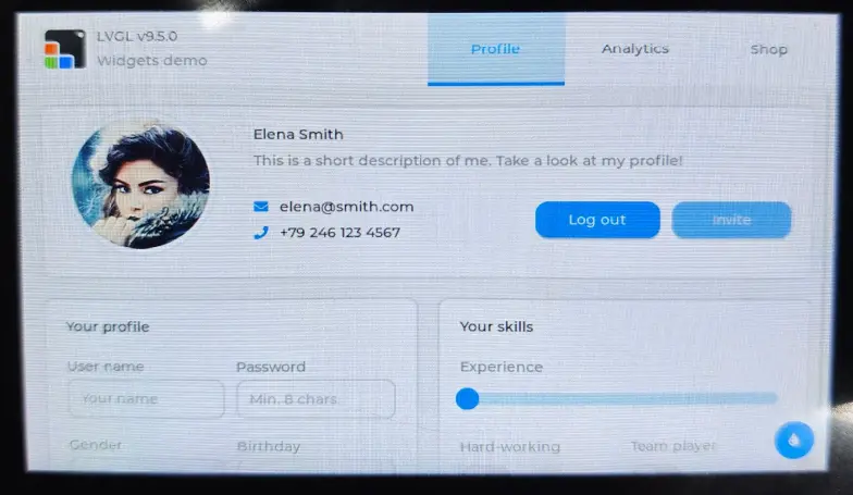
Power cycle the screen, and you will see the LVGL v9.5.0 Widgets example displayed on the screen. For the version with a touch panel, slide on the screen to test the touch function.