Section 07 Driving RGB565 Screen
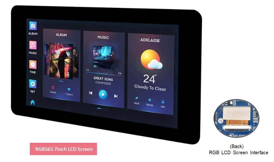
Regarding the development of various LCD displays, the ESP32-S3 currently supports interface types such as SPI (QSPI), I80, and RGB. On the ESP32-S3-Touch-LCD-7 we have integrated a 7-inch screen with an RGB565 interface. Compared to screens using other interfaces, the RGB interface can drive higher-resolution LCDs and achieve a higher refresh rate while consuming very little CPU time. It is perfectly suited for LVGL and is ideal for various smart development projects.
Pin Connections
Most RGB LCDs use an SPI + RGB interface, but this product uses only the RGB interface, making the driving method simpler and more direct.
The ESP32-S3 supports two color formats: 16-bit RGB565 and 8-bit RGB888. In this product we use 16-bit RGB565. The connection between the ESP32-S3 and the RGB screen is as follows: you need to connect HSYNC, VSYNC, PCLK, DE, and D0 ~ D15 (5 bits R + 6 bits G + 5 bits B).
| ESP32-S | LCD | Description |
|---|---|---|
| GPIO0 | G3 | Green data bit 3 |
| GPIO1 | R3 | Red data bit 3 |
| GPIO2 | R4 | Red data bit 4 |
| GPIO3 | VSYNC | Vertical sync signal |
| GPIO5 | DE | Data enable signal |
| GPIO7 | PCLK | Pixel clock signal |
| GPIO10 | B7 | Blue data bit 7 |
| GPIO14 | B3 | Blue data bit 3 |
| GPIO17 | B6 | Blue data bit 6 |
| GPIO18 | B5 | Blue data bit 5 |
| GPIO21 | G7 | Green data bit 7 |
| GPIO38 | B4 | Blue data bit 4 |
| GPIO39 | G2 | Green data bit 2 |
| GPIO40 | R7 | Red data bit 7 |
| GPIO41 | R6 | Red data bit 6 |
| GPIO42 | R5 | Red data bit 5 |
| GPIO45 | G4 | Green data bit 4 |
| GPIO46 | HSYNC | Horizontal sync signal |
| GPIO47 | G6 | Green data bit 6 |
| GPIO48 | G5 | Green data bit 5 |
| CH422G | LCD | Description |
|---|---|---|
| EXIO2 | DISP | Backlight enable pin |
Hardware Connection
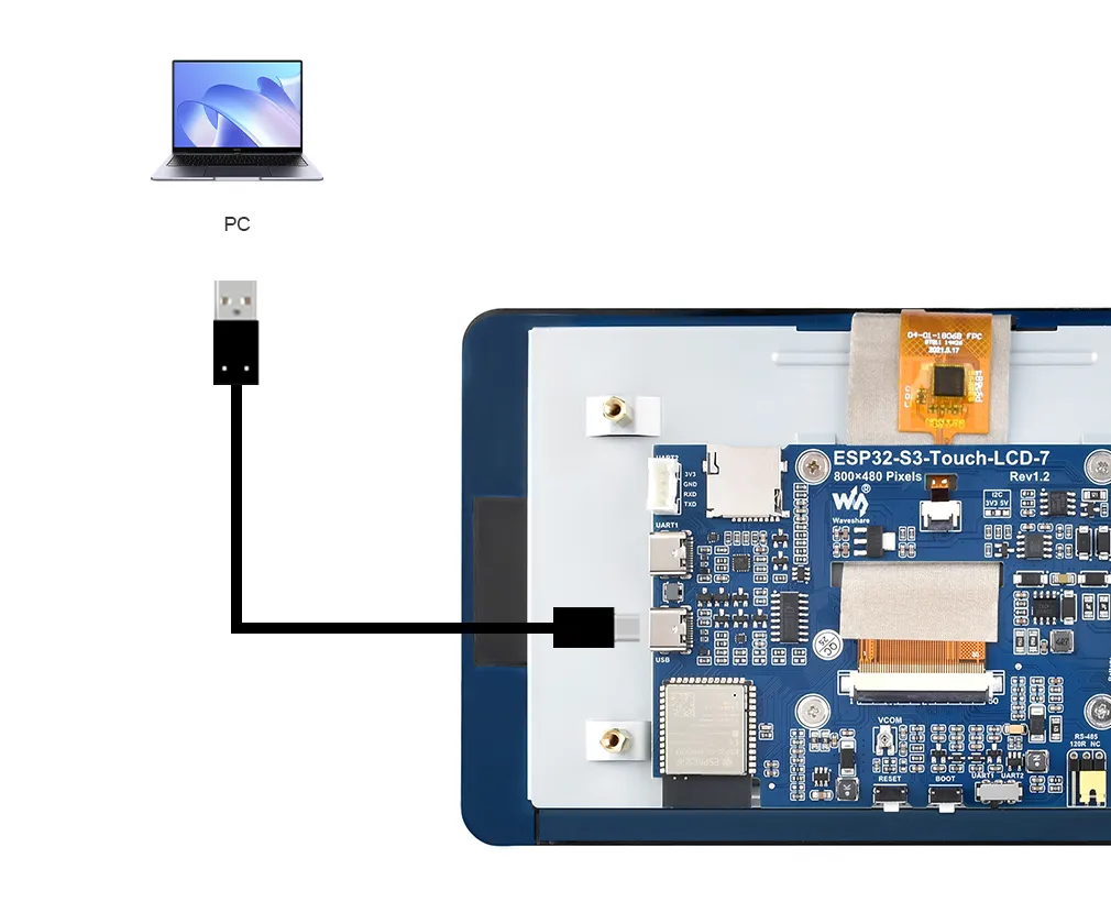
To upload the corresponding code to the ESP32-S3, you need to connect the USB port of the ESP32-S3-Touch-LCD-7 to the computer's USB port using a Type-C to Type-A cable:
Example
Please download the example package from the following address: ESP32-S3-Touch-LCD-7 Example (if already downloaded, simply open the corresponding folder).
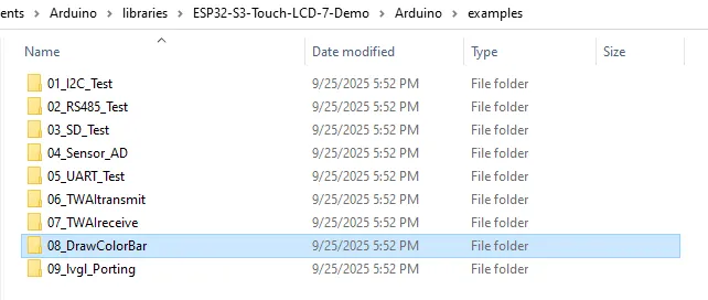
After extracting the example package, open the corresponding 08_DrawColorBar folder.
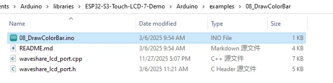
Double-click to open 08_DrawColorBar.ino:
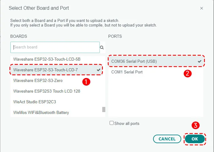
Select the board model "Waveshare ESP32-S3-Touch-LCD-7" and the port.
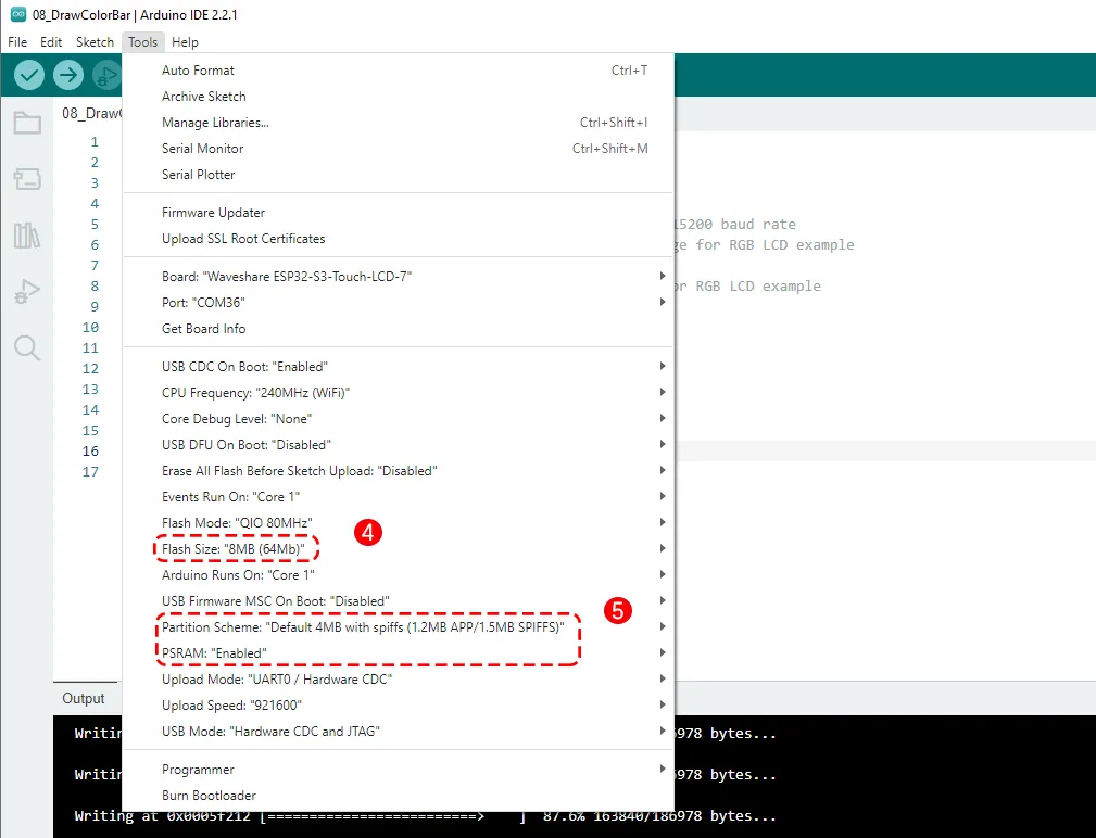
Then set the board parameters:
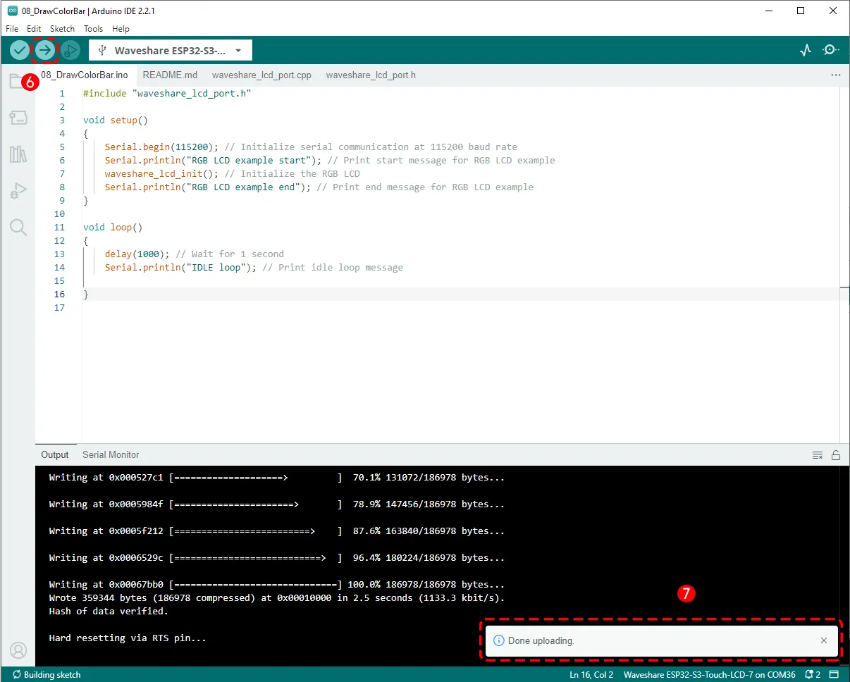
Then click the Upload button to upload the program, and wait for the upload to complete:
Running Results
After the program upload is complete, power-cycle the ESP32-S3-Touch-LCD-7. You will see the screen light up and display a gradient of three color bars.

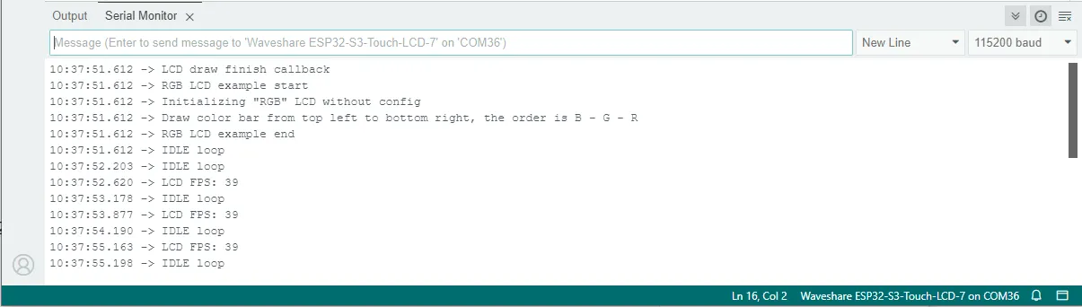
Open the Serial Monitor in the Arduino IDE; you will also see the printed output from the program as shown below:
Code Review
The screen has a built-in ST7262 driver IC. In the example we use the ESP_Display_Panel library to drive the screen. The pin definitions and initialization functions are defined in waveshare_lcd_port.h and waveshare_lcd_port.cpp.
- ESP_Display_Panel is a unified display driver library officially provided by ESP-IDF for driving various LCDs, RGB screens, and e-paper displays. It abstracts "bus → panel → touch" into standard interfaces, allowing you to quickly drive different display models without digging into hardware details.
- Using this library basically involves three steps: create a Bus object (handles low-level data transfer), create a Panel object (handles the specific LCD/EPD chip driver), and start drawing.
- If you need to use LVGL, you must create a binding between the Panel and the LVGL display driver.
1. In waveshare_lcd_port.h we define various parameters for the RGB screen
    #include <Arduino.h>
    #include <esp_display_panel.hpp>
Include the core header of the esp_display_panel library, which contains definitions for Bus/Panel/Touch. The library APIs we will use come from here.
    #define EXAMPLE_LCD_NAME                        ST7262 // LCD IC name, used by EXAMPLE_LCD_CLASS macro to build the class name
    #define EXAMPLE_LCD_WIDTH                       (800) // LCD width in pixels, matching the panel's actual resolution
    #define EXAMPLE_LCD_HEIGHT                      (480) // LCD height in pixels, matching the panel's actual resolution
    #define EXAMPLE_LCD_COLOR_BITS                  (24)  // LCD color depth, 24 means 24bpp per pixel
    #define EXAMPLE_LCD_RGB_DATA_WIDTH              (16)  // RGB data bus width, here it is 16-bit parallel
    #define EXAMPLE_LCD_RGB_COLOR_BITS          (16)   // RGB color depth is also 16-bit
These macros define the LCD panel parameters.
    #define EXAMPLE_LCD_RGB_TIMING_FREQ_HZ          (16 * 1000 * 1000) // RGB timing frequency
    #define EXAMPLE_LCD_RGB_TIMING_HPW              (4)   // Horizontal pulse width
    #define EXAMPLE_LCD_RGB_TIMING_HBP              (8)   // Horizontal back porch
    #define EXAMPLE_LCD_RGB_TIMING_HFP              (8)   // Horizontal front porch
    #define EXAMPLE_LCD_RGB_TIMING_VPW              (4)   // Vertical pulse width
    #define EXAMPLE_LCD_RGB_TIMING_VBP              (8)   // Vertical back porch
    #define EXAMPLE_LCD_RGB_TIMING_VFP              (8)   // Vertical front porch
    #define EXAMPLE_LCD_RGB_BOUNCE_BUFFER_SIZE  (EXAMPLE_LCD_WIDTH * 10)
This part defines the RGB timing parameters, directly corresponding to the HSYNC/VSYNC, front/back porch, pulse width (PW), and pixel clock frequency (PCLK) from the LCD datasheet. ** EXAMPLE_LCD_RGB_BOUNCE_BUFFER_SIZE** is the size of the "temporary buffer" allocated internally by the driver for smooth output; here it is set to width * 10.
    #define EXAMPLE_LCD_RGB_IO_DISP            (-1)  // RGB display pin number
    #define EXAMPLE_LCD_RGB_IO_VSYNC           (3)   // VSYNC pin number
    #define EXAMPLE_LCD_RGB_IO_HSYNC           (46)  // HSYNC pin number
    #define EXAMPLE_LCD_RGB_IO_DE              (5)   // Data enable pin number
    #define EXAMPLE_LCD_RGB_IO_PCLK            (7)   // Pixel clock pin number
    #define EXAMPLE_LCD_RGB_IO_DATA0           (14)  // RGB data pin 0
    ...
    #if EXAMPLE_LCD_RGB_DATA_WIDTH > 8
    #define EXAMPLE_LCD_RGB_IO_DATA8           (48)  // RGB data pin 8
    ...
    #endif
    #define EXAMPLE_LCD_RST_IO                 (-1)  // Reset pin number
    #define EXAMPLE_LCD_BL_IO            (-1)  // Backlight pin number
    #define EXAMPLE_LCD_BL_ON_LEVEL           (1)   // Backlight ON level
    #define EXAMPLE_LCD_BL_OFF_LEVEL !EXAMPLE_LCD_BL_ON_LEVEL // Backlight OFF level
This part maps the pins according to the hardware connections between the ESP32-S3 and the RGB screen.
IO_DISP, RST_IO, and BL_IO are connected to the I/O expander chip, so they are not defined here; a value of -1 is used, and the code will skip them. These three pins are actually pulled high by the hardware.
    #define EXAMPLE_LCD_ENABLE_CREATE_WITH_CONFIG   (0)
    #define EXAMPLE_LCD_ENABLE_PRINT_FPS            (1)
    #define EXAMPLE_LCD_ENABLE_DRAW_FINISH_CALLBACK (1)

    #if EXAMPLE_LCD_ENABLE_PRINT_FPS
    #define EXAMPLE_LCD_PRINT_FPS_PERIOD_MS         (1000)
    #define EXAMPLE_LCD_PRINT_FPS_COUNT_MAX         (50)
    #endif
EXAMPLE_LCD_ENABLE_CREATE_WITH_CONFIG: if 1, the LCD object is created via a "configuration structure"; if 0, a built-in creation function is used. Here we set it to 0.EXAMPLE_LCD_ENABLE_PRINT_FPS: when enabled, the library periodically prints the frame rate (for performance debugging). PRINT_FPS_PERIOD_MS is the print interval; COUNT_MAX sets the maximum number of frames for statistics, etc.EXAMPLE_LCD_ENABLE_DRAW_FINISH_CALLBACK: whether to trigger a callback when a frame drawing is finished (often used to notify the upper layer to release buffers or perform the next operation).
    #define _EXAMPLE_LCD_CLASS(name, ...) LCD_##name(__VA_ARGS__)
    #define EXAMPLE_LCD_CLASS(name, ...)  _EXAMPLE_LCD_CLASS(name, ##__VA_ARGS__)
These two lines are macro tricks that expand EXAMPLE_LCD_CLASS(ST7262, args...) into LCD_ST7262(args...). The purpose is to connect EXAMPLE_LCD_NAME to the actual class name/constructor, making it easier to write a generic create function.
void waveshare_lcd_init();
Declaration of the initialization function; its definition is given in the .cpp file.
2. The construction of the bus, panel, and other parts, as well as the screen initialization steps, are mainly in waveshare_lcd_port.cpp
First, there are two ways to create the BusRGB and the LCD (Panel) object: create_lcd_without_config() and create_lcd_with_config(), which are "macro shortcut construction" and "explicit configuration structure", respectively.
    static LCD *create_lcd_without_config(void)
    {
        BusRGB *bus = new BusRGB(
    #if EXAMPLE_LCD_RGB_DATA_WIDTH == 8
            /* 8-bit RGB IOs */
            EXAMPLE_LCD_RGB_IO_DATA0, EXAMPLE_LCD_RGB_IO_DATA1, EXAMPLE_LCD_RGB_IO_DATA2, EXAMPLE_LCD_RGB_IO_DATA3,
            EXAMPLE_LCD_RGB_IO_DATA4, EXAMPLE_LCD_RGB_IO_DATA5, EXAMPLE_LCD_RGB_IO_DATA6, EXAMPLE_LCD_RGB_IO_DATA7,
            EXAMPLE_LCD_RGB_IO_HSYNC, EXAMPLE_LCD_RGB_IO_VSYNC, EXAMPLE_LCD_RGB_IO_PCLK, EXAMPLE_LCD_RGB_IO_DE,
            EXAMPLE_LCD_RGB_IO_DISP,
            /* RGB timings */
            EXAMPLE_LCD_RGB_TIMING_FREQ_HZ, EXAMPLE_LCD_WIDTH, EXAMPLE_LCD_HEIGHT,
            EXAMPLE_LCD_RGB_TIMING_HPW, EXAMPLE_LCD_RGB_TIMING_HBP, EXAMPLE_LCD_RGB_TIMING_HFP,
            EXAMPLE_LCD_RGB_TIMING_VPW, EXAMPLE_LCD_RGB_TIMING_VBP, EXAMPLE_LCD_RGB_TIMING_VFP
    #elif EXAMPLE_LCD_RGB_DATA_WIDTH == 16
            /* 16-bit RGB IOs */
            EXAMPLE_LCD_RGB_IO_DATA0, EXAMPLE_LCD_RGB_IO_DATA1, EXAMPLE_LCD_RGB_IO_DATA2, EXAMPLE_LCD_RGB_IO_DATA3,
            EXAMPLE_LCD_RGB_IO_DATA4, EXAMPLE_LCD_RGB_IO_DATA5, EXAMPLE_LCD_RGB_IO_DATA6, EXAMPLE_LCD_RGB_IO_DATA7,
            EXAMPLE_LCD_RGB_IO_DATA8, EXAMPLE_LCD_RGB_IO_DATA9, EXAMPLE_LCD_RGB_IO_DATA10, EXAMPLE_LCD_RGB_IO_DATA11,
            EXAMPLE_LCD_RGB_IO_DATA12, EXAMPLE_LCD_RGB_IO_DATA13, EXAMPLE_LCD_RGB_IO_DATA14, EXAMPLE_LCD_RGB_IO_DATA15,
            EXAMPLE_LCD_RGB_IO_HSYNC, EXAMPLE_LCD_RGB_IO_VSYNC, EXAMPLE_LCD_RGB_IO_PCLK, EXAMPLE_LCD_RGB_IO_DE,
            EXAMPLE_LCD_RGB_IO_DISP,
            /* RGB timings */
            EXAMPLE_LCD_RGB_TIMING_FREQ_HZ, EXAMPLE_LCD_WIDTH, EXAMPLE_LCD_HEIGHT,
            EXAMPLE_LCD_RGB_TIMING_HPW, EXAMPLE_LCD_RGB_TIMING_HBP, EXAMPLE_LCD_RGB_TIMING_HFP,
            EXAMPLE_LCD_RGB_TIMING_VPW, EXAMPLE_LCD_RGB_TIMING_VBP, EXAMPLE_LCD_RGB_TIMING_VFP
    #endif
        );
        return new EXAMPLE_LCD_CLASS(
            EXAMPLE_LCD_NAME, bus, EXAMPLE_LCD_WIDTH, EXAMPLE_LCD_HEIGHT, EXAMPLE_LCD_COLOR_BITS, EXAMPLE_LCD_RST_IO
        );
    }
- Depending on
EXAMPLE_LCD_RGB_DATA_WIDTH(8 or 16), the appropriate constructor parameter list is selected. We set it to 16, so for 16-bit data width, the data pins (DATA0~DATA15), HSYNC, VSYNC, PCLK, DE, DISP, RGB timings, etc., are passed to the constructor to build theBusRGBobject. - Next,
EXAMPLE_LCD_CLASS(EXAMPLE_LCD_NAME, ...)is called, which expandsEXAMPLE_LCD_NAMEinto the class nameLCD_ST7262, resulting inLCD_ST7262(bus, EXAMPLE_LCD_WIDTH, EXAMPLE_LCD_HEIGHT, EXAMPLE_LCD_COLOR_BITS, EXAMPLE_LCD_RST_IO). It passes thebusand basic parameters (resolution, color depth, reset pin). This step creates the specific Panel (LCD) object and binds it to the bus.
static LCD *create_lcd_with_config(void)
The static LCD *create_lcd_with_config(void) function uses explicit configuration structures (BusRGB::Config, LCD::Config) to create the Bus and Panel, making the configuration clearer and more extensible. It constructs a BusRGB::Config bus_config to contain all display parameters, and an LCD::Config lcd_config to specify the reset pin, resolution, etc.
    DRAM_ATTR int frame_count = 0;
    DRAM_ATTR int fps = 0;
    DRAM_ATTR long start_time = 0;

    IRAM_ATTR bool onLCD_RefreshFinishCallback(void *user_data)
    {
        if (start_time == 0) {
            start_time = millis();

            return false;
        }

        frame_count++;
        if (frame_count >= EXAMPLE_LCD_PRINT_FPS_COUNT_MAX) {
            fps = EXAMPLE_LCD_PRINT_FPS_COUNT_MAX * 1000 / (millis() - start_time);
            esp_rom_printf("LCD FPS: %d\n", fps);
            frame_count = 0;
            start_time = millis();
        }

        return false;
    }
    #endif // EXAMPLE_LCD_ENABLE_PRINT_FPS

    #if EXAMPLE_LCD_ENABLE_DRAW_FINISH_CALLBACK
    IRAM_ATTR bool onLCD_DrawFinishCallback(void *user_data)
    {
        esp_rom_printf("LCD draw finish callback\n");

        return false;
    }
    #endif
- This code counts the real frame rate (FPS) in the LCD refresh completion interrupt callback, using IRAM/DRAM safe practices.**
onLCD_RefreshFinishCallback()** is the LCD refresh completion callback function. It is called by the driver each time a frame refresh completes. It counts frames, and when the count reachesEXAMPLE_LCD_PRINT_FPS_COUNT_MAX(set to 50 in the .h file), it calculates and prints the FPS. onLCD_DrawFinishCallback()is the callback for completing a draw operation; it prints a simple message.
void waveshare_lcd_init(void)
This is the main entry point that ties everything together to actually start the screen. Let's examine each step.
    #if EXAMPLE_LCD_ENABLE_CREATE_WITH_CONFIG
        Serial.println("Initializing \"RGB\" LCD with config");
        auto lcd = create_lcd_with_config();
    #else
        Serial.println("Initializing \"RGB\" LCD without config");
        auto lcd = create_lcd_without_config();
    #endif
Depending on the macro, either the "with config" or "without config" method is used to create the LCD pointer. In the header file we set EXAMPLE_LCD_ENABLE_CREATE_WITH_CONFIG to 0, so we use create_lcd_without_config() to create the object.
    auto bus = static_cast<BusRGB *>(lcd->getBus());
    bus->configRGB_BounceBufferSize(EXAMPLE_LCD_RGB_BOUNCE_BUFFER_SIZE); // Set bounce buffer to avoid screen drift
- Obtain the Bus pointer from the LCD and cast it to
BusRGB*, then call the configuration function to set the "bounce buffer" size. Bounce buffer: in parallel RGB drivers, an intermediate buffer is often used to handle data timing and avoid display drift (when the driver cannot continuously supply pixel data, the buffer fills the gap). Here we set a pixel-sized buffer to balance memory usage and stability.
lcd->init();
This is the crucial initialization call. It actually enters the initialization function of LCD_ST7262, which performs various configurations and creates the RGB Panel ( esp_lcd_new_rgb_panel), completing all low-level preparations for building the RGB LCD driver.
    #if EXAMPLE_LCD_ENABLE_PRINT_FPS
        // Attach a callback function which will be called when the Vsync signal is detected
        lcd->attachRefreshFinishCallback(onLCD_RefreshFinishCallback);
    #endif
    #if EXAMPLE_LCD_ENABLE_DRAW_FINISH_CALLBACK
        // Attach a callback function which will be called when every bitmap drawing is completed
        lcd->attachDrawBitmapFinishCallback(onLCD_DrawFinishCallback);
    #endif
Attach the two callback functions, which will be called after a frame refresh is finished and after a draw operation is completed, respectively.
assert(lcd->begin());
Finalizes the preparation work from init(), then starts and executes the panel initialization commands. assert() is used to ensure that begin() returns success (boolean true); a failure will trigger an assertion, helping to quickly locate initialization failure issues.
    if (lcd->getBasicAttributes().basic_bus_spec.isFunctionValid(LCD::BasicBusSpecification::FUNC_DISPLAY_ON_OFF)) {
        lcd->setDisplayOnOff(true);
    }
Check and turn on the display.
    Serial.println("Draw color bar from top left to bottom right, the order is B - G - R");
    lcd->colorBarTest();
colorBarTest() is a built-in test function that draws a set of color bars (blue-green-red) to quickly visually verify the display effect.
3. Main program DrawColorBar.ino
    Serial.begin(115200); // Initialize serial communication at 115200 baud rate
    Serial.println("RGB LCD example start"); // Print start message for RGB LCD example
    waveshare_lcd_init(); // Initialize the RGB LCD
    Serial.println("RGB LCD example end"); // Print end message for RGB LCD example
In the void setup() function, the serial port is initialized and waveshare_lcd_init() is called.