Section 02 Debugging RS485 Interface
The ESP32-S3 chip has three UART controllers that support the half-duplex RS485 protocol, using differential signals for data transmission. Compared to RS232, it offers longer transmission distances and higher data rates. To convert single-ended signals to differential signals, an external RS485 transceiver is required to drive and receive RS485 signals.
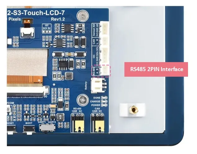
In this product, we use IO15 and IO16 of the ESP32-S3 as the TX and RX pins for RS485 respectively. These pins are connected to the SP3485EN transceiver, and a PH2.0 2PIN connector is provided for customers to connect to various RS485 devices for communication and control.
Below is a simple connection diagram. For the detailed hardware connection, please refer to our schematic.

In this tutorial, we will use this port to communicate with a PC, providing a simple RS485 loopback example that even beginners can quickly understand how to drive the RS485 interface for communication.
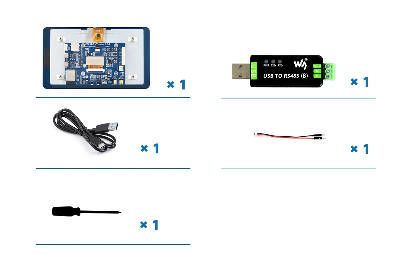
Required Components
The components required for this example are:
- ESP32-S3-Touch-LCD-7 x1
- USB TO RS485 (B) module x1
- USB cable Type-A male to Type-C male x1
- HY2.0 2PIN to male cable x1
- Flathead screwdriver x1
Hardware Connection
-
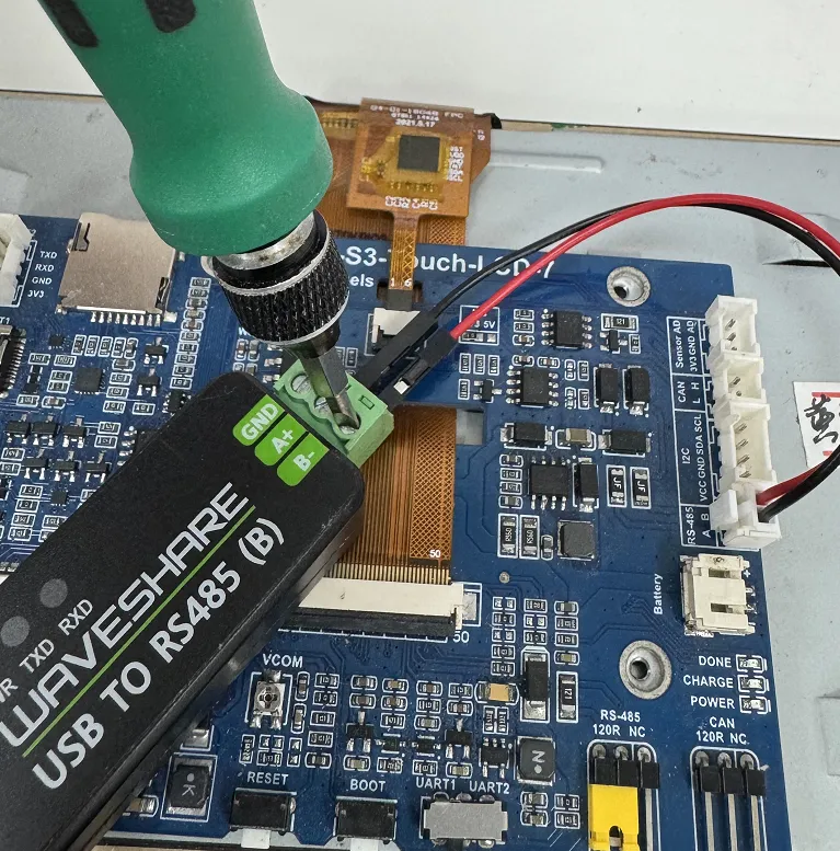
First connect the supplied 2PIN male cable connector to the white RS485 interface, ensuring good contact between the wire and the connector.
-
Connect the RS485 A terminal of the ESP32-S3-Touch-LCD-7 to the A+ terminal of the USB TO RS485 (B) module, and similarly connect the B terminal to the B- terminal. Use a flathead screwdriver to adjust the screws on the USB TO RS485 module's connector, clamping the pins of the black and red wires to ensure a firm and stable connection.
-
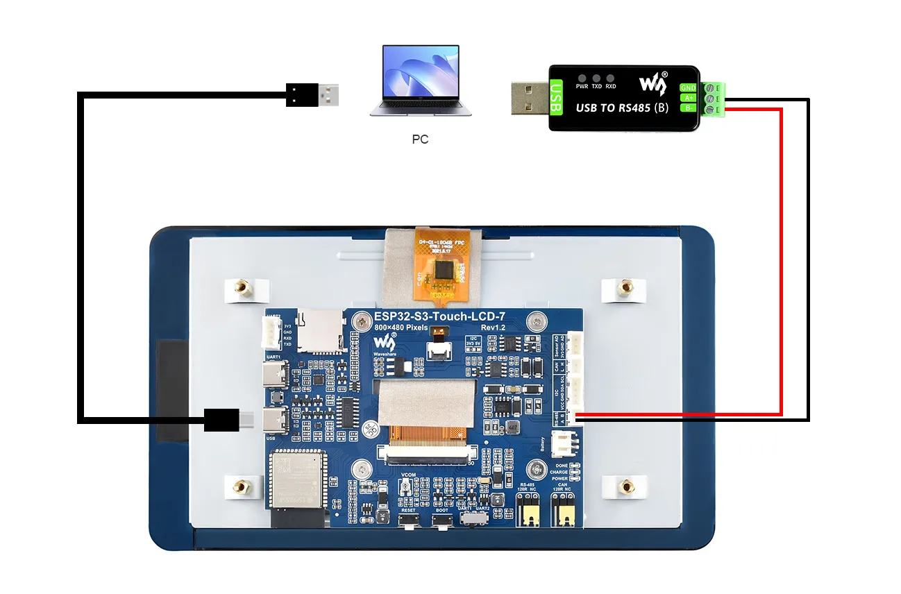
Then plug the USB port of the USB TO RS485 (B) into the computer's USB port.
-
Use a Type-A male to Type-C USB cable to also connect the USB port of the ESP32 to the computer for downloading the program and viewing serial debug information. The complete connection is shown below:
 Hardware Analysis
PIN15 is used as the RS485 receive pin, PIN16 as the RS485 transmit pin, connected to the RS485 transceiver chip, which converts to RS485 interface signals. The RS485 interface is then connected to the USB TO RS485 (B) module, converting to USB signals, and finally to the PC for communication.
Example
Please download the example package from the following address: ESP32-S3-Touch-LCD-7 Example (if already downloaded, simply open the corresponding folder).
After extracting the example package, open the \Arduino\examples\02_RS485_Test folder.
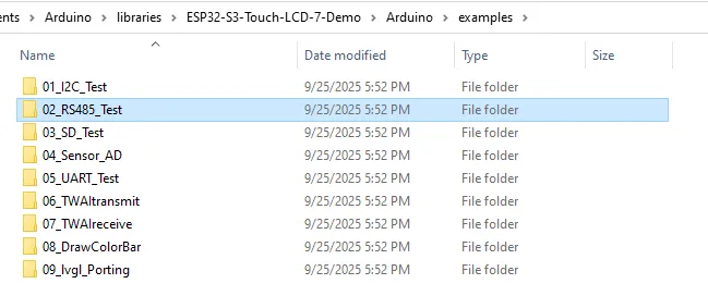
Double-click to open 02_RS485_Test.ino:

We have already connected the USB port for downloading the program. After opening the program, select the correct serial port and board model "Waveshare ESP32-S3-Touch-LCD-7" in the upper right corner.
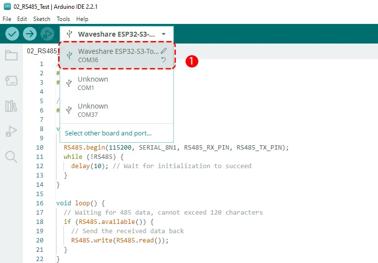
Because two USB devices are now connected, the computer will recognize an additional COM port – that is the COM port of the USB TO RS485 (B) module. When uploading the program, be careful to select the COM port that was previously recognized for the ESP32-S3. (Of course, if you mistakenly select the COM port of the USB TO RS485 (B) module, the download will fail; then you can select the other COM port and it will succeed.)
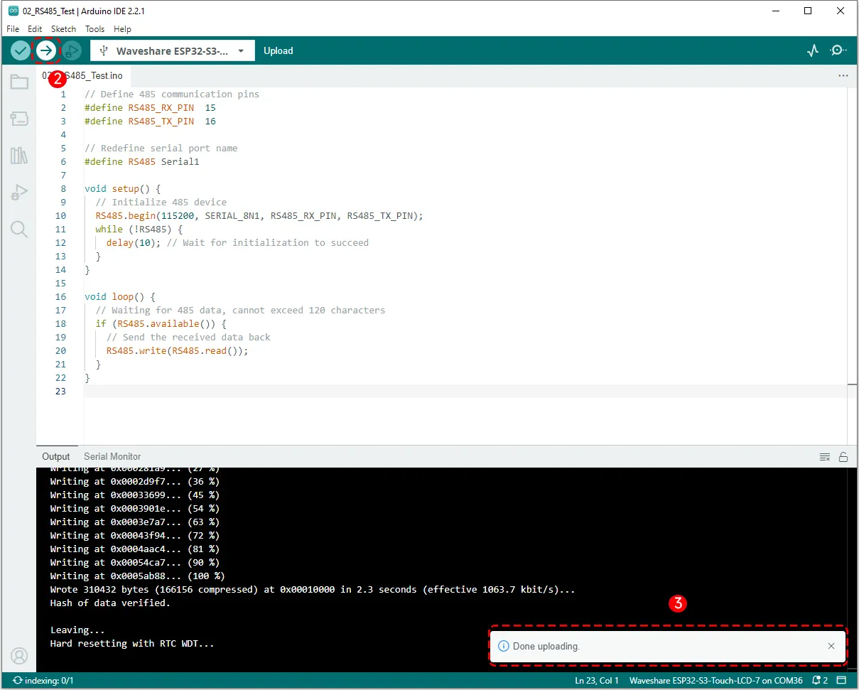
Then click the Upload button to upload the program, and wait for the upload to complete.
Running Results
After the program upload is complete, proceed with RS485 debugging. At this point we need to use a serial debug tool like SSCOM. After downloading and installing it, open the serial debug tool and follow the steps below to configure it.
Send the string "waveshare" to the RS485 serial port of the ESP32-S3. When the program reads it, it immediately returns the same characters to the PC, thus implementing a simple RS485 loopback.
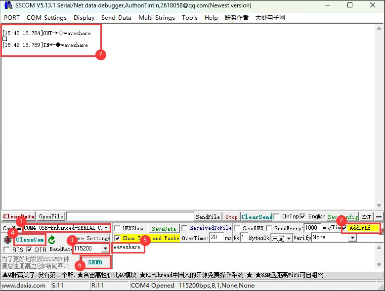
In step 1 of the image, when selecting the COM port, pay attention to choose the one labeled "USB-Enhanced-SERIAL CH343". That is the COM port corresponding to the USB TO RS485 (B) module, through which the PC mainly communicates.
Code Review
    // Define 485 communication pins
    #define RS485_RX_PIN 15
    #define RS485_TX_PIN 16

    // Redefine serial port name
    #define RS485 Serial1

    void setup() {
      // Initialize 485 device
      RS485.begin(115200, SERIAL_8N1, RS485_RX_PIN, RS485_TX_PIN);
      while (!RS485) {
        delay(10); // Wait for initialization to succeed
      }
    }

    void loop() {
      // Waiting for 485 data, cannot exceed 120 characters
      if (RS485.available()) {
        // Send the received data back
        RS485.write(RS485.read());
      }
    }
- First,
#defineis used to define the RS485 receive pin as 15 and the transmit pin as 16, and the nameSerial1is redefined asRS485. - In the
void setup()function,RS485.begin(i.e., Serial1.begin) initializes the serial port baud rate to115200, data formatSERIAL_8N1(8 data bits), with receive and transmit pins 15 and 16 respectively. Then awhile()loop ensures that the serial initialization is successful. - In the
void loop()function, theifstatement checks whether data is available on the serial port. If data is available, it reads one byte and immediately writes it back, implementing the function of echoing the received RS485 data unchanged.