Section 04 Testing Sensor AD Interface
In the natural world, most physical quantities are analog signals, such as temperature, light, voltage, current, sound, pressure, and gas concentration. These change continuously, but an MCU is digital logic and can only read combinations of 0 and 1. Therefore, the ADC (Analog-to-Digital Converter) serves as the bridge from the analog world to the digital world.
The ESP32-S3 supports a total of 20 measurement channels: ADC1 channels: GPIO1 - GPIO10; ADC2 channels: GPIO11 - GPIO20. For specific definitions, refer to the official datasheet. For an ADC driver tutorial on the ESP32-S3 in the Arduino IDE, you can study our ESP32 Tutorial ADC Analog Input.
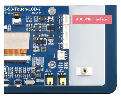
On this product, we bring out IO6 as the ADC pin and integrate a PH2.0 3PIN Sensor AD header, making it convenient for customers to connect sensors with analog output.
To help users quickly become familiar with the AD interface, we provide a simple analog signal reading example, as well as an example of connecting an MQ-7 Gas Sensor to read and convert gas sensor data. This helps beginners understand how to modify the basic code to drive their own ADC devices.
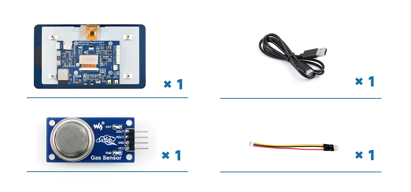
Required Components
- ESP32-S3-Touch-LCD-7 x1
- USB cable Type-A male to Type-C male x1
- MQ-7 Gas Sensor gas sensor x1
- HY2.0 3P to male cable x1
Basic Code
Please download the example package from the following address: ESP32-S3-Touch-LCD-7 Example (if already downloaded, simply open the corresponding folder).
After extracting the example package, open the \Arduino\examples\04_Sensor_AD folder.
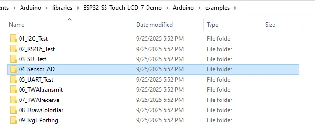
Double-click to open 04_Sensor_AD.ino.

Here we provide a simple analog signal reading example. Users can modify this code to interface their own analog signal sensors. We will explain it briefly below.
    #include <Arduino.h>
    #define PIN_ADC2_CH2 6  //Define the pin macro
Include the Arduino header file and give GPIO6 the name PIN_ADC2_CH2 to make the code more readable.
    void setup() {
    Serial.begin(115200);      //The serial port is initially configured
    analogReadResolution(12);  //Set ADC resolution to 12 bits (0-4096)
    }
In the setup() initialization phase, open serial communication with a baud rate of 115200, and set the ADC read resolution to 12 bits (0 to 4095). 12-bit means 4096 steps; higher resolution gives finer precision. Lower resolution makes values jump more. ESP32 defaults to 12-bit, but it is good practice to explicitly set it.
Next, in the loop() main loop, the ESP32 continuously reads the ADC and prints the results.
    int analogOriginalValue = 0;
    int analogVoltsValue = 0;
Define two variables: one to store the raw ADC value (0-4095), and one to store the converted voltage value (in mV).
analogOriginalValue = analogRead(PIN_ADC2_CH2);
Read the analog voltage on GPIO6, returning a number between 0 and 4095. This is a raw digital value without units.
analogVoltsValue = analogReadMilliVolts(PIN_ADC2_CH2);
Directly returns the voltage value, in millivolts (mV), without manual calculation. analogReadMilliVolts()** is a function specific to the ESP32 Arduino framework; it automatically converts the raw ADC value to a readable voltage.
    Serial.printf("ADC analog value = %d\n",analogOriginalValue);
    Serial.printf("ADC millivolts value = %d mV\n",analogVoltsValue);
Output the raw value and the voltage value to the Serial Monitor.
delay(100);
A 100ms delay after each read to reduce serial spam, stabilize the ADC output, and make data observation easier.
Using Basic Code to Read Sensor Data
Now we will modify the basic code above to read the analog signal from an MQ-7 Gas Sensor and print the read and converted results.
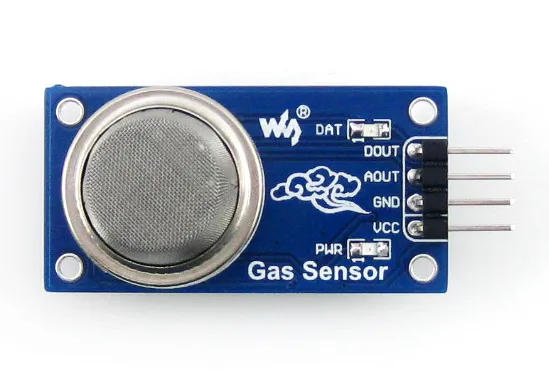
1. MQ-7 Gas Sensor Product Introduction
This is a gas sensor introduced by Waveshare, mainly used to detect carbon monoxide. Inside the sensor is a gas-sensitive element made of metal oxide. When it comes into contact with a specific gas, its conductivity changes. The sensor converts this conductivity change into two output signals: analog output and digital output.
Pin functions:
- VCC: Positive power supply. Connect to a DC voltage of 2.5V to 5.0V. It powers the entire sensor module.
- GND: Ground. Connect to the negative terminal of the power supply and common ground with your MCU.
- AOUT: Analog output. This pin outputs a continuously changing voltage.
- DOUT: Digital output. This pin outputs only two states: high or low.
2. Hardware Connection
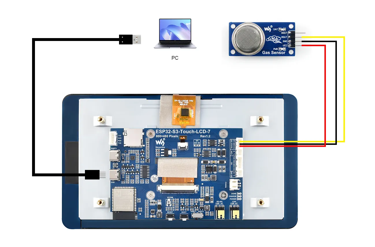
For this test, we only need to use the AOUT pin. Connect the sensor to the Sensor AD interface of the ESP32-S3-Touch-LCD-7 as shown: GND to GND, VCC to 3V3, AOUT to AD. Also connect the ESP32's USB port to the computer using a Type-A male to Type-C USB cable for programming and viewing serial debug information.
The complete connection is shown below:
3. Code Modification
Rewrite the code as follows:
    #include <Arduino.h>
    #define gas_ain 6
    int ad_value = 0;
    int ad_voltsvalue = 0;
    void setup()
    {
    pinMode(gas_ain,INPUT);
    Serial.begin(115200);
    analogReadResolution(12);
    }
    void loop()
    {
    ad_value=analogRead(gas_ain);
    ad_voltsvalue = analogReadMilliVolts(gas_ain);
    Serial.printf("gas analog value = %d\n",ad_value);
    Serial.printf("gas millivolts value = %d mV\n",ad_voltsvalue);

    delay(1000);
    }
The AOUT pin of the sensor connects to GPIO6, so we set #define gas_ain 6 and configure this pin as an input in void setup().
Before use, the sensor should be preheated for one minute (to heat the sensitive material inside so it works properly). You can add the following code in setup():
    Serial.println("\n=== Gas Sensor Initialization ===");
    Serial.println("Sensor warming up... Please wait 60 seconds");

    // Preheating wait
    for(int i = 60; i > 0; i--) {
        Serial.printf("Warm-up countdown: %d seconds\n", i);
        delay(1000);
    }
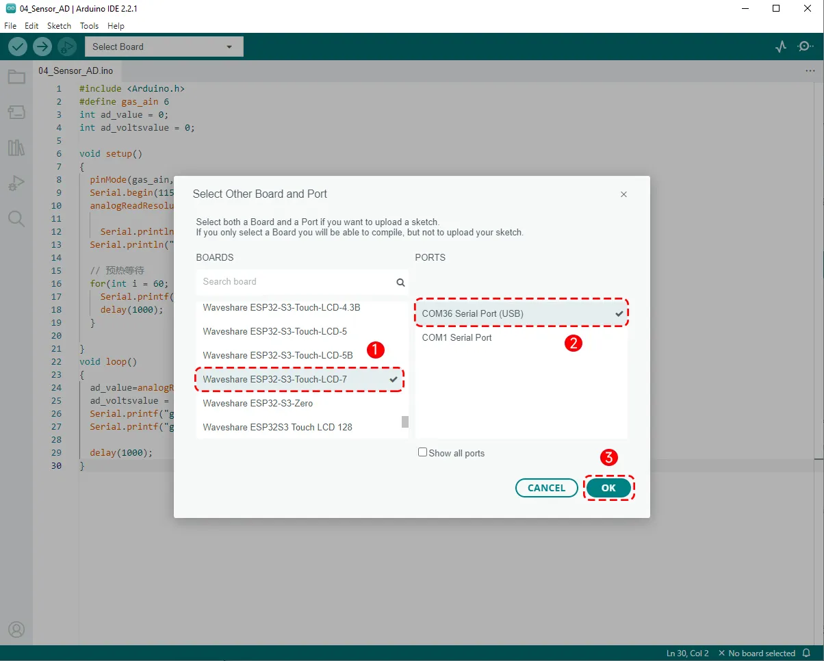
4. Code Upload
We have already connected the USB port for downloading the program. After opening the program, select the correct serial port and board model "Waveshare ESP32-S3-Touch-LCD-7" in the upper right corner:
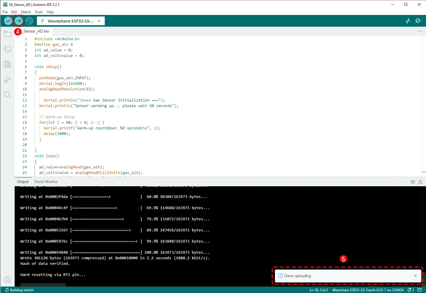
Then click the Upload button to upload the program, and wait for the upload to complete.
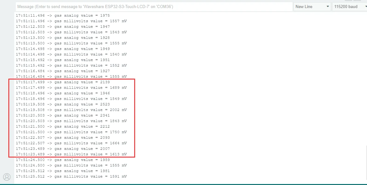
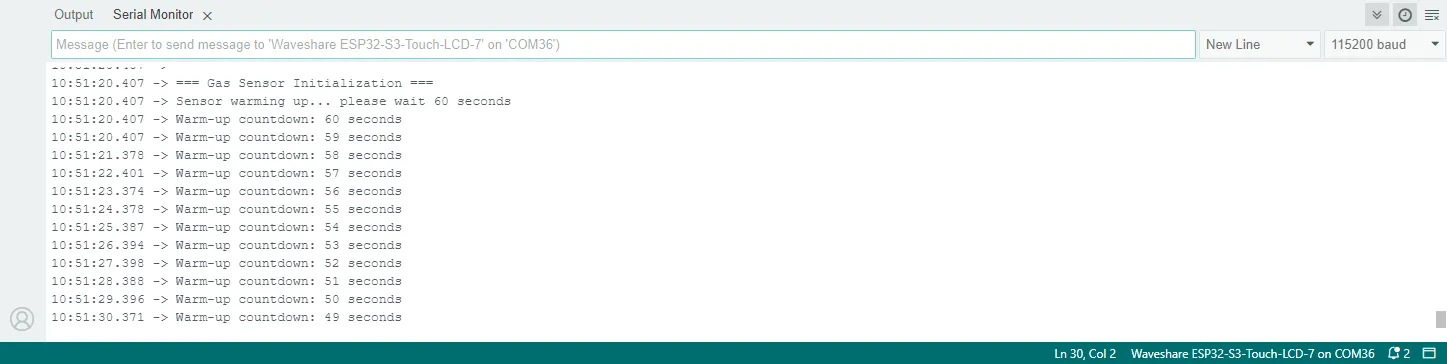
5. Running Results
After the program is successfully uploaded, open the Serial Monitor from the Tools menu, set the baud rate to 115200, and you will see that the program is running and preheating the sensor:
Blow a breath of air onto the sensor, and you will see the serial output values change, indicating that the sensor is working properly.