ESP32-C3-Zero
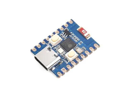
- ESP32-C3-Zero (Without header)
- ESP32-C3-Zero-M (With pre-soldered header)
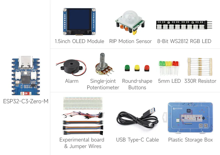
- ESP32-C3-Zero-Basic-Kit (Basic Kit)

The ESP32-C3-Zero (Without header) and ESP32-C3-Zero-M (With pre-soldered header) are compact modules featuring castellated holes, making them easy to integrate into other carrier boards. The ESP32-C3-Zero features an on-board Type-C USB connector and breaks out most available pins in a small form factor. It utilizes the ESP32-C3FH4, a System-on-Chip (SoC) that integrates low-power Wi-Fi and BLE 5, along with 4MB of Flash. Additionally, it includes hardware cryptographic accelerators, RNG, HMAC, and a Digital Signature module, meeting IoT security requirements and offering rich peripheral interfaces. Its various low-power operating states satisfy the power consumption needs of application scenarios such as the Internet of Things (IoT), mobile devices, wearable electronics, and smart homes.
The ESP32-C3-Zero-Basic-Kit (Basic Kit) includes the ESP32-C3-Zero-M and the ESP32-XX-Basic-Kit-Acce kit, equipped with a breadboard, wires, LEDs, resistors, a 1.5-inch OLED, and other modules. It provides the core hardware needed to learn the Waveshare ESP32 Arduino Tutorial and Waveshare ESP32 MicroPython Tutorial, making it suitable for getting started quickly with Arduino, MicroPython, and ESP-IDF programming. Relevant example programs and wiring diagrams can be downloaded here: ESP32-C3-Zero-Basic-Kit-main.zip (GitHub Repository).
| SKU | Product |
|---|---|
| 25452 | ESP32-C3-Zero |
| 25532 | ESP32-C3-Zero-M |
| 33358 | ESP32-C3-Zero-Basic-Kit |
Features
- Equipped with the ESP32-C3FH4 chip, featuring a RISC-V 32-bit single-core processor running at up to 160 MHz.
- Supports 2.4GHz Wi-Fi (802.11 b/g/n) and Bluetooth® 5 (LE).
- Built-in 400KB SRAM and 384KB ROM, with 4MB stacked Flash.
- Uses a castellated module design with an on-board ceramic antenna, facilitating integration into user-designed baseboards.
- Supports flexible clock settings and independent module power control to realize multi-scenario low-power modes.
- Integrated USB Serial full-speed controller, breaking out 15 GPIOs for flexible peripheral configuration.
- Features peripherals including 3 × SPI, 1 × I2C, 2 × UART, 1 × I2S, 2 × ADC, etc.
Onboard Resources

- USB Type-C Port
- BOOT Button: Hold this button and then press the RESET button to enter download mode.
- RESET Button
- WS2812 RGB LED
- ME6217C33M5G: Low Dropout Regulator (LDO), max output current 800mA.
- ESP32-C3FH4: Main frequency up to 160MHz.
- 2.4G Ceramic Antenna
Hardware Description
- When using the ESP32-C3-Zero as a daughter board, ensure the ceramic antenna area is kept clear. Avoid covering the ceramic antenna with the PCB, metal, or plastic components.
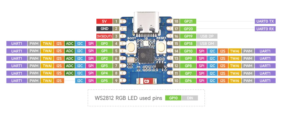
- On the ESP32-C3-Zero, GPIO12~GPIO17 are not broken out as these pins are used for the stacked 4MB Flash.
- The ESP32-C3-Zero uses GPIO10 to connect the WS2812 RGB LED. For the WS2812 datasheet, please refer to this link.
- The ESP32-C3-Zero does not use a USB-to-UART bridge chip. To download firmware, you must hold the BOOT (GPIO9) button before connecting the Type-C cable.
- The TX and RX silkscreen markings on the board represent the ESP32-C3-Zero's default UART0 pins, where TX is GPIO21 and RX is GPIO20.
- The board's IO pins support a voltage of 3.3V.
Hardware Connection
- Every time you download firmware, hold the BOOT (GPIO9) button before connecting the Type-C cable.
- When powered by an external source, input a 3.7V~6V power supply at the pad marked "5V".
Pinout
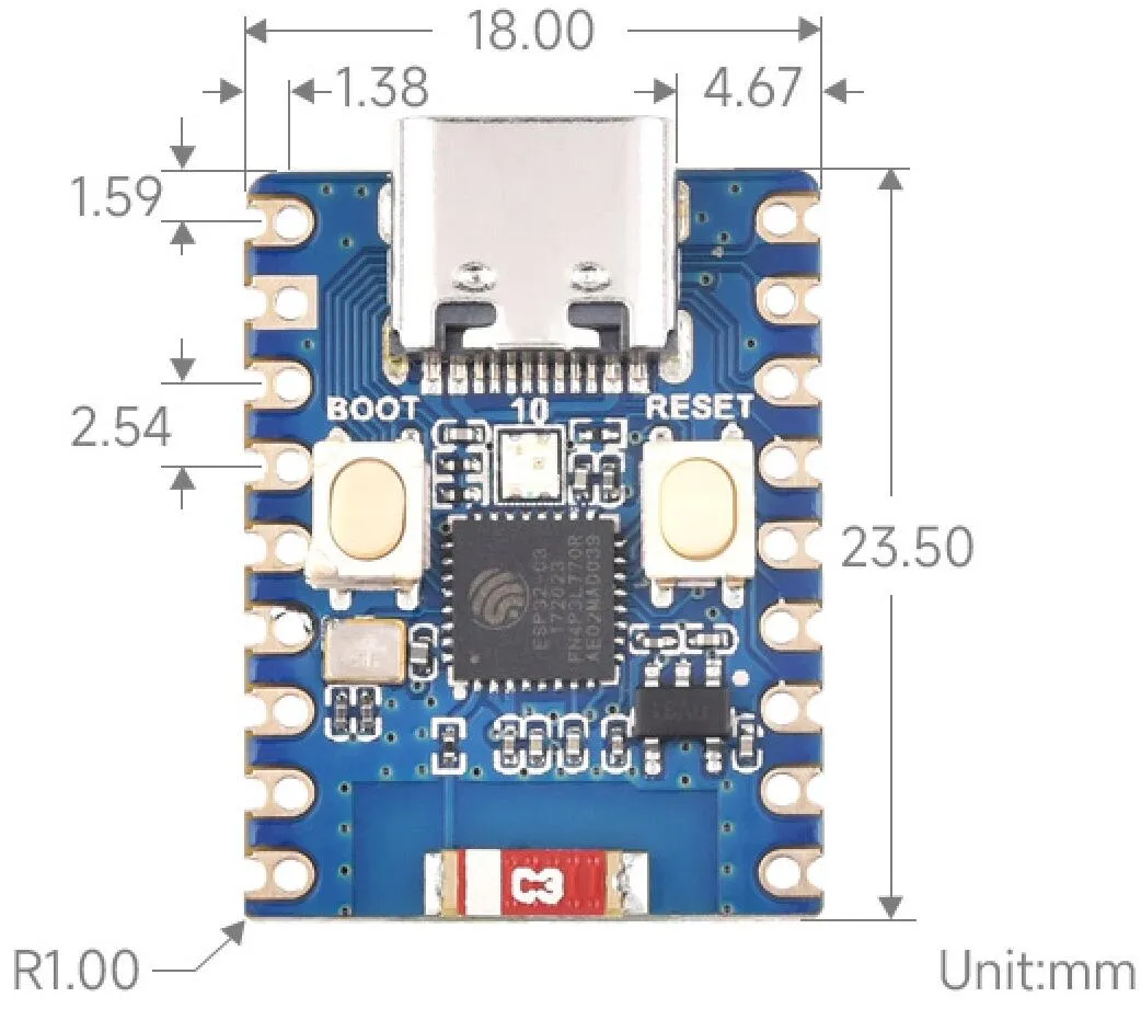
Dimensions