ESP32-P4-WIFI6-Touch-LCD-X
- 7inch Kit
- 8inch Kit
- 10.1inch Kit
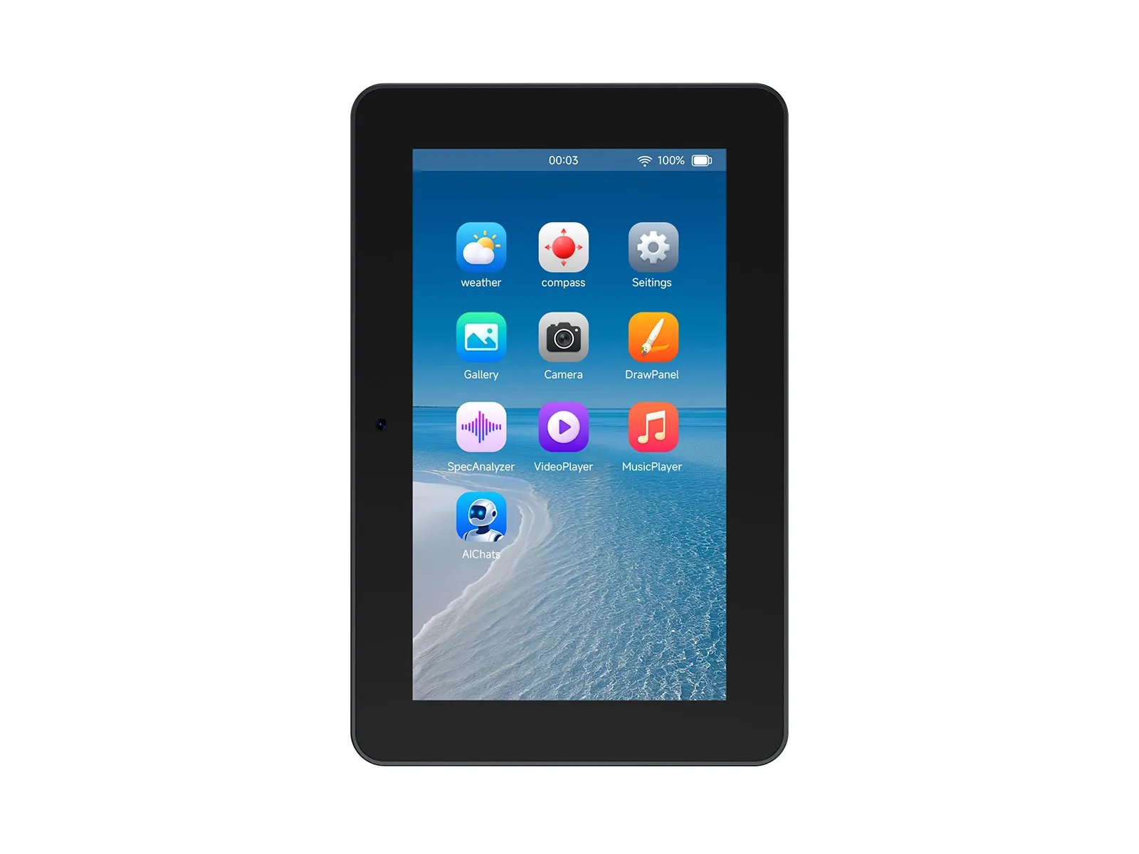
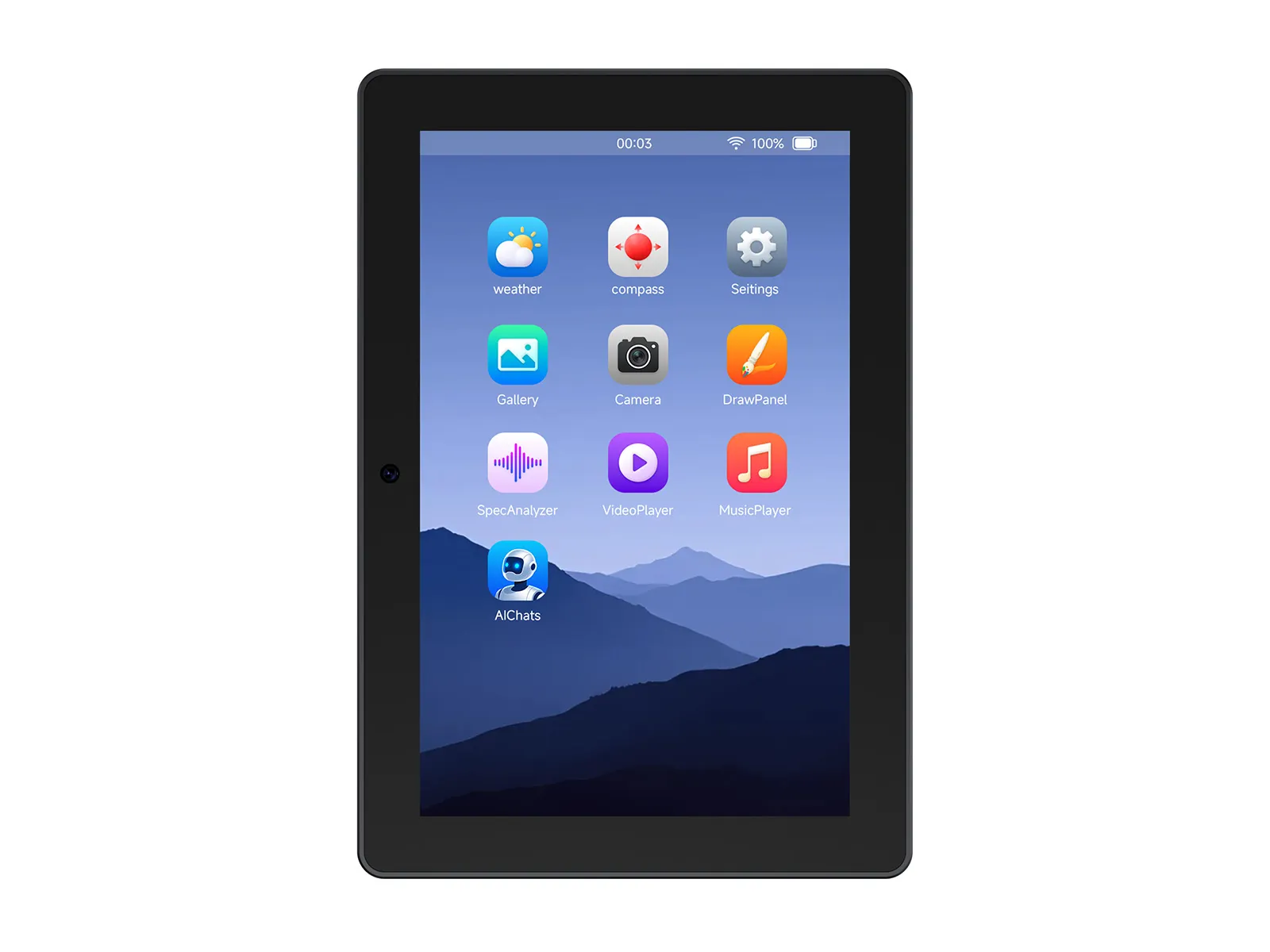
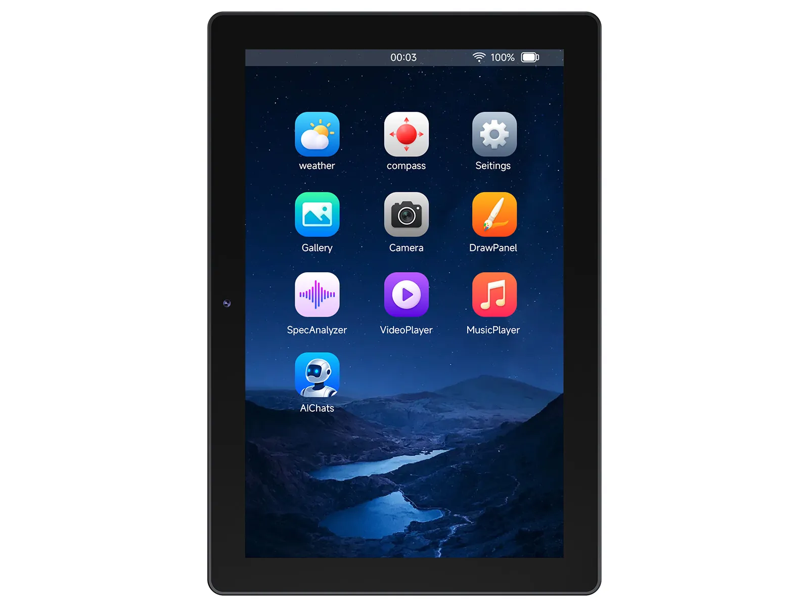
This series is a high-performance development board based on the ESP32-P4 chip, featuring a dual-core plus single-core RISC-V architecture. It comes with a 7 / 8 / 10.1inch IPS touch display, supports rich human-machine interaction interfaces, includes MIPI-CSI (with an integrated Image Signal Processor, ISP), and also supports USB 2.0 OTG HS for high-speed connectivity. The ESP32-P4 chip integrates a digital signature peripheral and a dedicated key management unit to ensure data and operational security. It is designed for high performance and high security applications, and fully meets the higher requirements of embedded applications for human-computer interface support, edge computing capabilities and IO connection features.
| SKU | Product |
|---|---|
| 30738 | ESP32-P4-WIFI6-Touch-LCD-7 |
| 33147 | ESP32-P4-WIFI6-Touch-LCD-7-EN |
| 33673 | ESP32-P4-WIFI6-Touch-LCD-8 |
| 33149 | ESP32-P4-WIFI6-Touch-LCD-8-EN |
| 33672 | ESP32-P4-WIFI6-Touch-LCD-10.1 |
| 33150 | ESP32-P4-WIFI6-Touch-LCD-10.1-EN |
Features
- Processor
- Equipped with a RISC-V 32-bit dual-core processor (HP system), featuring DSP and ISA extensions, a Floating-Point Unit (FPU), with a main frequency of up to 360 MHz.
- Equipped with a RISC-V 32-bit single-core processor (LP system), with a main frequency of up to 40 MHz.
- Equipped with an ESP32-C6 WIFI/BT co-processor, expanding WIFI 6/Bluetooth 5 and other functions through SDIO
- Memory
- 128 KB of high-performance (HP) system read-only memory (ROM).
- 16 KB of low-power (LP) system read-only memory (ROM).
- 768 KB of high-performance (HP) L2 memory (L2MEM).
- 32 KB of low-power (LP) SRAM.
- 8 KB of system tightly coupled memory (TCM).
- Stacked 32MB PSRAM within the chip package, and externally integrated 32MB Nor Flash.
- Peripheral Interfaces
- Onboard peripherals including MIPI-CSI, MIPI-DSI, USB 2.0 OTG, an SDIO 3.0 TF card slot, dual microphones (supports echo cancellation), and speaker, etc.
Hardware Description
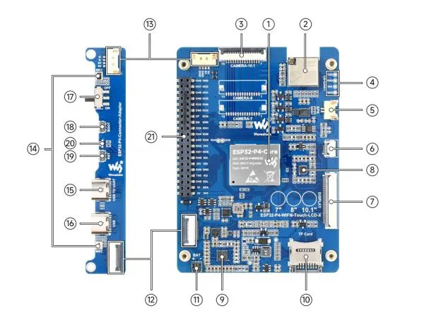
- ESP32-P4-Core Integrates ESP32-P4NRW32 and 32MB Nor Flash
- ESP32-C6-MINI-1U-H8 module SDIO interface protocol, extending Wi-Fi 6 / Bluetooth 5 (LE)
- MIPI CSI interface 15PIN pitch 1.0mm interface for connecting MIPI-2lane camera
- 2.54mm 4PIN pads Used for ESP32-C6 module firmware flashing
- Speaker header 1.25mm 2PIN
- Touch panel connector Supports touch function expansion
- DSI display connector Used for connecting display devices and data transmission
- ES8311 low-power audio codec chip Handles audio encoding and decoding tasks
- ES7210 Echo cancellation algorithm chip Effectively eliminates echo and improves audio capture accuracy
- TF card slot Utilizes the SDIO 3.0 interface protocol, supporting storage expansion
- Battery header A JST 2Pin connector with 1.2mm pitch, suitable for external battery power supply
- Board-to-Board signal transmission interfaces Designed for a 16Pin 0.5mm pitch FPC cable, enabling signal communication between boards
- Board-to-Board power supply & common ground interfaces Designed for an ultra-thin 1.25mm 4Pin header cable, ensuring stable power and common ground connection
- Onboard microphones Features a dual-microphone array design, optimizing audio capture performance
- USB TO UART Type-C port Provides power supply, firmware flashing, and debugging capabilities
- USB OTG Type-C port A USB OTG 2.0 High-Speed interface supporting peripheral expansion
- Power supply ON/OFF switch Controls the device's power on/off state.
- BOOT button Presses it when powering on or resetting to enter download mode
- RESET button Used for device reset operations
- PWR & Charge dual-color indicator Serve as a power indicator and a charging indicator, visually displaying device status
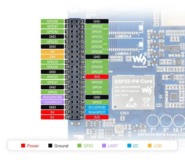
- 40PIN header Provides a general-purpose expansion interface, supporting connection of various peripherals and function expansion
Pinout Definition
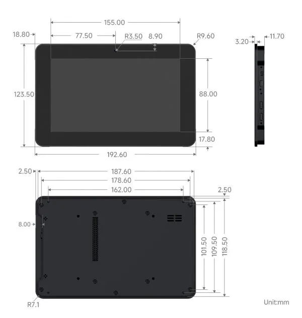
Dimensions
ESP32-P4-WIFI6-Touch-LCD-7
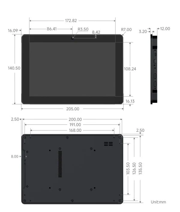
ESP32-P4-WIFI6-Touch-LCD-8
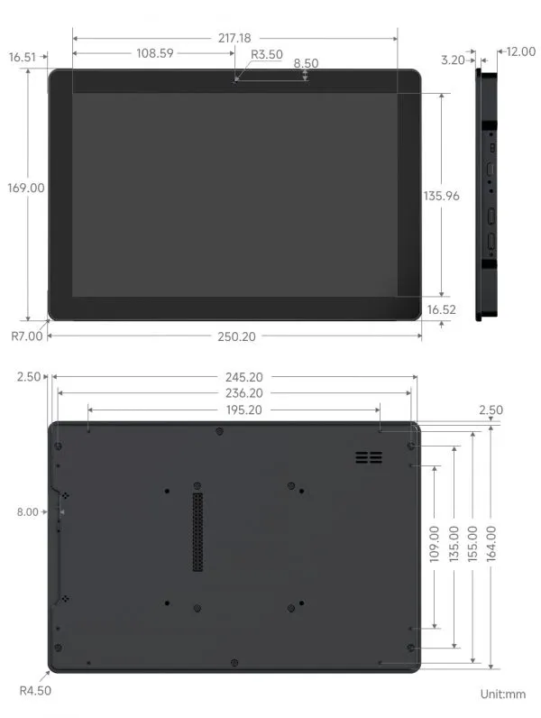
ESP32-P4-WIFI6-Touch-LCD-10.1
Development Tools
Each of these two development approaches has its own advantages, and developers can choose according to their needs and skill levels. Arduino is suitable for beginners and non-professionals because they are easy to learn and quick to get started. ESP-IDF is a better choice for developers with a professional background or high performance requirements, as it provides more advanced development tools and greater control capabilities for the development of complex projects.
Due to the limited support for ESP32-P4 on the Arduino platform, ESP-IDF is currently recommended for development.
- ESP-IDF, short for Espressif IoT Development Framework, is a development framework provided by Espressif for the ESP series chips. It is developed using the C language, including a compiler, debugger, and flashing tool, etc., and can be developed via the command lines or through an integrated development environment (such as Visual Studio Code with the Espressif IDF plugin). The plugin offers features such as code navigation, project management, and debugging, etc. We recommend using VS Code for development. For the specific configuration process, please refer to the Working with ESP-IDF. The tutorial also provides relevant demos for reference.