Working with MicroPython
This chapter contains the following sections. Please read as needed:
MicroPython Getting Started Tutorial
New to Pico MicroPython development and want to get started quickly? We have prepared a general introductory tutorial for you. These tutorial is designed to help developers quickly become familiar with Thonny IDE and start developing. It covers environment setup, project creation, component usage, and peripheral programming, helping you take the first step in MicroPython programming.
- Section 1 Basic Introduction
- Section 2 GPIO
- Section 3 PWM
- Section 4 ADC
- Section 5 UART
- Section 6 I2C
- Section 7 SPI
- Section 8 PIO
Setting Up Development Environment
Please refer to the Install and Configure Thonny IDE Tutorial to download and install the Thonny IDE.
Example
The MicroPython demos are located in the Micropython directory of the example package.
| Demo | Basic Program Description | Dependency Library |
|---|---|---|
| 01_GUI | LCD GUI display program | - |
| 02_SD | Mount TF card | - |
| 03_RTC | Get RTC data | - |
| 04_IMU | Get six-axis sensor data | - |
01_GUI
Description
- Use SPI to communicate with the LCD and implement touch tracking on the LCD via GUI.
Hardware Connection
- Connect the board to the computer using a USB cable
Code Analysis
lcd = lcd_st7789(): Create an LCD object.touch = touch_ft6336u(): Initialize the touch object.points = touch.get_touch_xy(): Get touch point coordinates.lcd.draw_square(): Draw a point and display it on the LCD.
Operation Result
-
Upload all .py files from the
01_GUIfolder to the development board using Thonny, and run the RP2350-Touch-LCD-3.5.py program.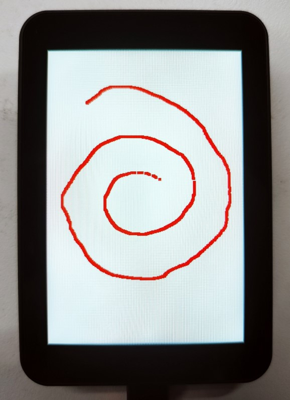
02_SD
Description
- Uses SPI to communicate with the TF card and mounts the TF card to the development board. After successful mounting, you can view and modify the contents of the TF card via Thonny.
Hardware Connection
- Insert a TF card
- Connect the board to the computer using a USB cable
Code Analysis
sdcard.SDCard(spi, cs, baudrate): Creates a TF card object and binds the initialized SPI interface and CS pin to the TF card driver.uos.mount(sd, '/sd'): Mounts the TF card file system to the/sddirectory. After successful mounting, users can perform file read/write operations on the TF card via the/sdpath, such as creating, reading, or deleting files.
Operation Result
-
Upload all py files from the
02_SDfolder to the development board via Thonny and reset the board. After resetting, the development board will automatically mount the TF card to thesddirectory according to the boot.py program.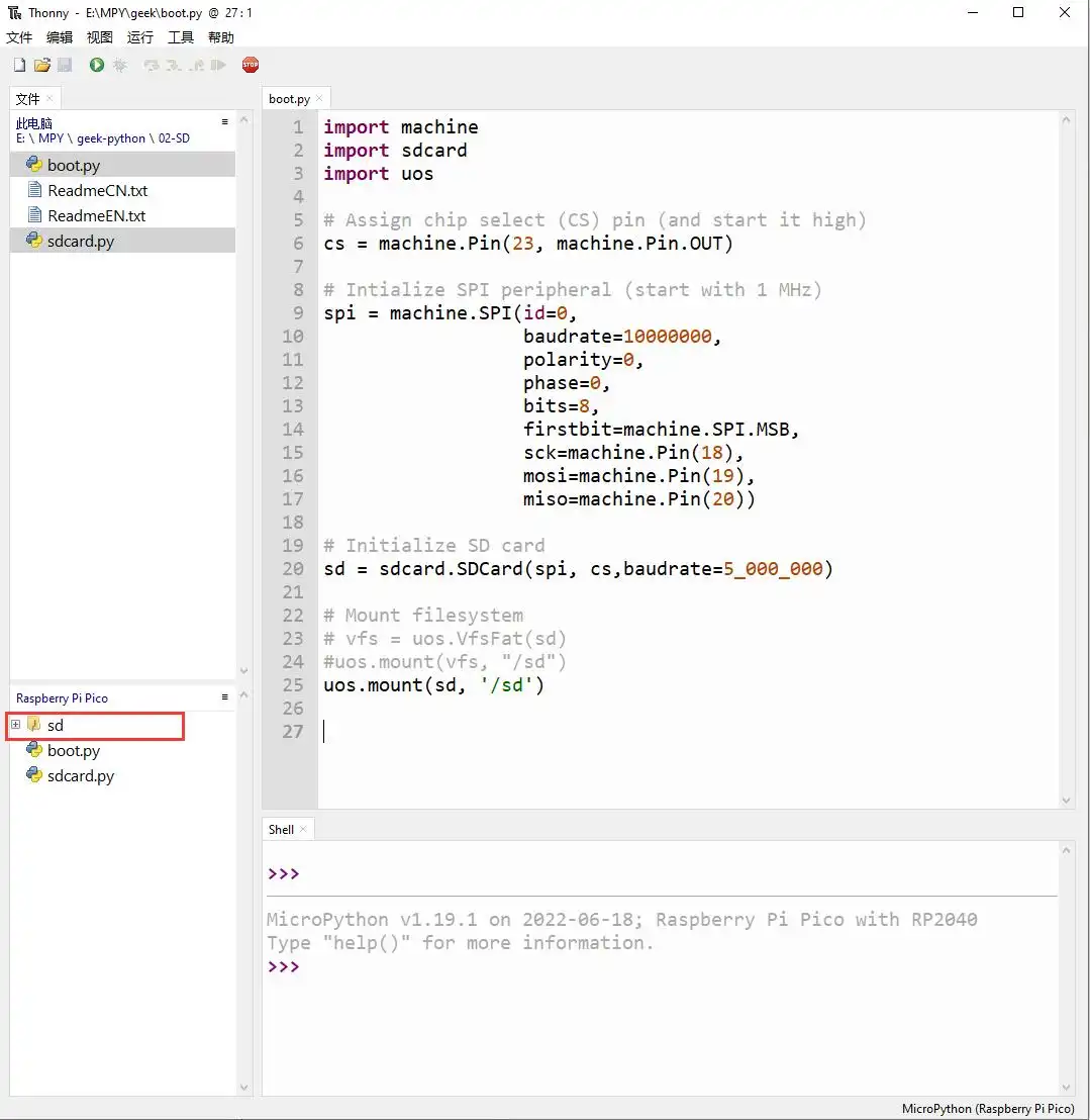
03_RTC
Description
- Uses I2C to communicate with the onboard RTC chip, sets and reads RTC time data, and tests if the RTC interrupt is functioning correctly.
Hardware Connection
- Connect the board to the computer using a USB cable
Code Analysis
RTC = PCF85063(): Creates an RTC object.RTC.setDate(weekday, day, month, year): Sets the RTC date.RTC.setTime(hour, minute, second): Sets the RTC time.RTC.readTime(): Reads the RTC time.RTC.setAlarm(second, minute, hour, day, weekday): Sets the RTC alarm.RTC.enableAlarm(): Enables the RTC alarm.
Operation Result
-
Run the py files in the
03_RTCfolder using Thonny.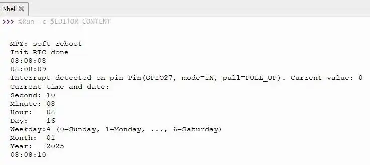
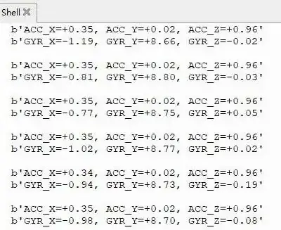
04_IMU
Description
- Uses I2C to communicate with the onboard six-axis sensor and reads the sensor data.
Hardware Connection
- Connect the board to the computer using a USB cable
Code Analysis
IMU = QMI8658(): Creates an IMU object.IMU.Read_XYZ(): Reads the six-axis sensor data.
Operation Result
-
Run the py files in the
04_IMUfolder using Thonny.