I2C Communication
The core logic of this tutorial applies to all ESP32 boards, but all the operation steps are explained using the example of the Waveshare ESP32-S3-Zero mini development board. If you are using a development board of another model, please modify the corresponding settings according to the actual situation.
I2C (Inter-Integrated Circuit), also known as I²C or IIC, is a widely used two-wire serial communication protocol. The I2C protocol allows devices to communicate via two signal lines and is commonly used to connect peripherals such as sensors, displays, and memory.
I2C has the following characteristics:
-
Two-wire communication: Only two signal lines, SDA (data line) and SCL (clock line), are required.
-
Master-slave architecture: Supports multiple master devices (controllers) and slave devices (targets) on the same bus.
infoI²C specification -- Rev. 7.0 has updated the traditional terms "Master/Slave" terminology to "Controller/Target”. To ensure compatibility with existing code and documentation, this tutorial may mix these two expressions depending on the context.
-
Addressing: Each device has a unique 7-bit or 10-bit address.
-
Synchronous communication: Data transfer is synchronized via a clock line, making it more reliable.
The bus contains the following signal lines:
- SDA (Serial Data Line): Serial data line, used for transmitting data
- SCL (Serial Clock Line): Serial clock line, provided by the master device with the clock signal
When connecting actual hardware, all I2C devices also need to be connected to ground (GND) to ensure a common ground circuit.

The I2C protocol specification requires that there must be pull-up resistors on both the SDA and SCL lines. This is because the I2C bus uses an open-drain circuit structure, where devices can only pull the signal line to a low level and cannot actively output a high level. The function of the pull-up resistor is to pull the signal line back to a high level when the bus is idle, ensuring normal communication.
Case of adding external pull-up resistors:
- When connecting in actual use (especially for external modules or multi-board communication), it is recommended to connect a 4.7kΩ pull-up resistor to 3.3V on each SDA and SCL to improve communication reliability.
- When the bus is long, there are many devices, or the communication is unstable, external pull-up resistors must be used.
Cases where external pull-up resistors can be omitted:
- Many I2C modules (such as the Waveshare 1.5inch OLED Module used in this tutorial) have built-up resistors inside. These modules can often be connected directly without the need for additional pull-up resistors.
- The ESP32 GPIO supports internal weak pull-up, which can be used in simple applications. However, the best practice is still to add an external pull-up resistor to ensure stable communication.
If you are unsure whether a module includes a pull-up resistor, it is recommended to check the module schematic or datasheet.
1. I2C in ESP32
The number of I2C controllers built into the ESP32 series chips varies by specific model (typically 1 or 2), and the ESP32-S3-Zero development board used in this tutorial has 2 I2C controllers. Each I2C controller can be used as a master device or a slave device, and can be assigned to most GPIO pins.
The ESP32 I2C library is based on the Arduino Wire library and implements some additional APIs. For details, please refer to this document.
Wireobject: corresponds to the first I2C controller (I2C0) by default.Wire1object: corresponds to the second I2C controller (I2C1), which can be used simultaneously with Wire to achieve two independent I2C communications.- Custom pins: You can initialize I2C and specify the SDA and SCL pins by calling
Wire.begin(int sda, int scl).
When selecting SDA/SCL pins, be careful to avoid pins already occupied by other functions (such as onboard UART, LED). For specific pins, please refer to the schematic or pin diagram of the development board used.
2. Example 1: I2C Scanner
When connecting a new I2C module, you first need to know its address. Many modules do not have addresses or can be changed via jumpers. The I2C scanner program can quickly detect and report the addresses of all devices on the bus, making it an essential tool for I2C development and debugging.
2.1 Circuit Assembly
Components required:
- Waveshare 1.5inch OLED Module * 1 (can also be replaced with other I2C modules)
- 4.7kΩ resistor * 2 (optional, if the I2C module has a built-in pull-up resistor, it can be omitted)
- Breadboard * 1
- Wire
- ESP32 development board
Connect the circuit according to the wiring diagram below:
ESP32-S3-Zero Pinout Diagram

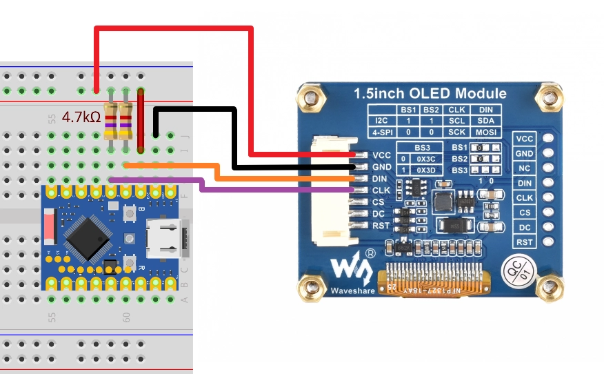
The 4.7k Ω pull-up resistor in the circuit diagram is the standard connection for I2C. Since the OLED module used in this tutorial has a built-in pull-up resistor, the circuit can still work properly without connecting these two resistors.
| Development board pins | OLED module | Description |
|---|---|---|
| GPIO 1 | DIN(SDA) | I2C data cable. Connect a 4.7kΩ pull-up resistor to 3.3V as needed |
| GPIO 2 | CLK(SCL) | I2C clock cable. Connect a 4.7kΩ pull-up resistor to 3.3V as needed |
| 3.3V | VCC | Power positive terminal |
| GND | GND | Power negative terminal |
2.2 Code
#include <Wire.h>

#define SDA_PIN 1  // You can select any available GPIO that corresponds to the actual wiring
#define SCL_PIN 2  // You can select any available GPIO that corresponds to the actual wiring

void setup() {
  Serial.begin(9600);
  Wire.begin(SDA_PIN,SCL_PIN);
}

void loop() {
  byte error, address;
  int nDevices = 0;

  delay(5000);

  Serial.println("Scanning for I2C devices ...");
  for (address = 0x01; address < 0x7f; address++) {
    Wire.beginTransmission(address);
    error = Wire.endTransmission();
    if (error == 0) {
      Serial.printf("I2C device found at address 0x%02X\n", address);
      nDevices++;
    } else if (error != 2) {
      Serial.printf("Error %d at address 0x%02X\n", error, address);
    }
  }
  if (nDevices == 0) {
    Serial.println("No I2C devices found");
  }
}
2.3 Code Analysis
#include <Wire.h>: Introduces the Arduino I2C communication library.Wire.begin(SDA_PIN, SCL_PIN): Initializes the I2C bus as a master device. On the ESP32, the function has multiple forms:Wire.begin(): Does not specify a pin, uses the default I2C pin defined for the current development board, such as GPIO 21 (SDA) and GPIO 22 (SCL). The schematic or pin definition of the board used shall prevail.Wire.begin(SDA_PIN, SCL_PIN): Use the specified GPIO pin. The pin numbers defined in the code must match the physical connections on the hardware.
for (address = 0x01; address < 0x7f; address++): Loop through all possible 7-bit I2C addresses.Wire.beginTransmission(address): The ESP32 (master device) attempts to establish communication with the specifiedaddress.Wire.endTransmission(): Ends the communication attempt and returns a status code.0: Success, the slave device has responded (ACK).2: The slave device did not respond (NACK) when receiving the address. This is the most common case, indicating that there is no device at the address.3: The slave device did not respond (NACK) when receiving the data.4: Other errors.
Serial.printf("I2C device found at address 0x%02X\n", address);: If the device is found, print its address in hexadecimal format (e.g.,0x27or0x3C).
2.4 Running Results
-
Upload the code, open the serial monitor, and set the appropriate baud rate (9600). The serial monitor will display the message "I2C device found at address ...".
The address that follows indicates the address of the I2C device, such as
0x3D.Scarming for I2C devices ...I2C device found at address 0x3D -
The program runs every 5 seconds, and the serial monitor continuously refreshes.
-
After disconnecting the I2C device, the serial monitor will display the prompt "No I2C devices found".
3. Example 2: Interact with the Module via I2C
In practical applications, developers usually don't need to write the underlying I2C data transceiver code themselves, but directly use hardware-specific libraries. This example will demonstrate how to drive an OLED screen with a SSD1327 control chip, which is a typical I2C application case.
It is worth noting that many Arduino libraries were originally designed for development boards with fixed I2C pins (such as Arduino Uno). In contrast, the I2C functionality of ESP32 is very flexible and can be mapped to most GPIO pins. Therefore, mastering how to configure custom I2C pins for these libraries is a key skill.
3.1 Circuit Assembly
Components required:
- Waveshare 1.5inch OLED Module * 1
- 4.7kΩ resistor * 2 (optional, if the I2C module has a built-in pull-up resistor, it can be omitted)
- Breadboard * 1
- Wire
- ESP32 development board
Connect the circuit according to the wiring diagram below:
ESP32-S3-Zero Pinout Diagram
The 4.7k Ω pull-up resistor in the circuit diagram is the standard connection for I2C. Since the OLED module used in this tutorial has a built-in pull-up resistor, the circuit can still work properly without connecting these two resistors.
| Development board pins | OLED module | Description |
|---|---|---|
| GPIO 1 | DIN(SDA) | I2C data cable. Connect a 4.7kΩ pull-up resistor to 3.3V as needed |
| GPIO 2 | CLK(SCL) | I2C clock cable. Connect a 4.7kΩ pull-up resistor to 3.3V as needed |
| 3.3V | VCC | Power positive terminal |
| GND | GND | Power negative terminal |
3.2 Code
This code example relies on the "Adafruit_SSD1327" library. Please search for and install the "Adafruit_SSD1327" library in the Arduino IDE's library manager.
For installation methods, please refer to: Arduino library manager tutorial.
- Using Wire
- Using Wire1
#include <Adafruit_SSD1327.h>  // SSD1327 OLED display library
#include <Wire.h>              // I2C communication library

// I2C pin definition
#define SDA_PIN 1      // Data cable
#define SCL_PIN 2      // Clock cable
#define OLED_RESET -1  // Reset pin

// Create a display object
Adafruit_SSD1327 display(128, 128, &Wire, OLED_RESET);

void setup() {
  // Initialize I2C bus
  Wire.begin(SDA_PIN, SCL_PIN);

  Serial.begin(9600);
  Serial.println("SSD1327 OLED test");

  // Connect the I2C device at address 0x3D
  if (!display.begin(0x3D)) {
    Serial.println("Unable to initialize OLED");
    while (1) yield();
  }

  // Display settings
  display.clearDisplay();
  display.setRotation(3);
  display.setTextSize(2);
  display.setTextColor(SSD1327_WHITE);

  // Display text
  display.setCursor(10, 10);
  display.println("Hello,");
  display.setCursor(40, 30);
  display.setTextColor(SSD1327_BLACK, SSD1327_WHITE);
  display.println(" World!");
  display.display();

  delay(1000);
}

void loop() {
}
#include <Adafruit_SSD1327.h>  // SSD1327 OLED display library
#include <Wire.h>              // I2C communication library

// I2C pin definition
#define SDA_PIN 1      // Data cable
#define SCL_PIN 2      // Clock cable
#define OLED_RESET -1  // Reset pin

// Create a display object
Adafruit_SSD1327 display(128, 128, &Wire1, OLED_RESET);

void setup() {
  // Initialize I2C bus
  Wire1.begin(SDA_PIN, SCL_PIN);

  Serial.begin(9600);
  Serial.println("SSD1327 OLED test");

  // Connect the I2C device at address 0x3D
  if (!display.begin(0x3D)) {
    Serial.println("Unable to initialize OLED");
    while (1) yield();
  }

  // Display settings
  display.clearDisplay();
  display.setRotation(3);
  display.setTextSize(2);
  display.setTextColor(SSD1327_WHITE);

  // Display text
  display.setCursor(10, 10);
  display.println("Hello,");
  display.setCursor(40, 30);
  display.setTextColor(SSD1327_BLACK, SSD1327_WHITE);
  display.println(" World!");
  display.display();

  delay(1000);
}

void loop() {
}
3.3 Code Analysis
This example demonstrates the typical workflow of using a third-party library and custom I2C pins on ESP32, where the core lies in correctly initializing and passing the Wire object to the library.
-
#define SDA_PIN 1and#define SCL_PIN 2: Use macro definitions to specify the GPIO pins used for I2C communication. This makes the code easy to modify and maintain. -
Wire.begin(SDA_PIN, SCL_PIN);: This is a key step. On the ESP32 platform, theWire.begin(SDA_PIN, SCL_PIN)function can remap the default I2C controller (Wireobject) to any specified SDA and SCL pins. After executing this line of code, all subsequent operations on theWireobject will be performed through GPIO 1 and GPIO 2. -
Adafruit_SSD1327 display(128, 128, &Wire, OLED_RESET);: Creates an instance of the object that displays the library.128, 128: Screen resolution (width and height).&Wire: Passes the address of theWireobject instance that has already been configured with pins to the library. The Adafruit library uses this pointer to call I2C functions (such asbeginTransmission,write,endTransmission, etc.) to communicate with the OLED screen.OLED_RESET: Reset pin. Setting to-1means no hardware reset is used.
This process leverages the flexibility of the ESP32 Arduino core library, allowing many libraries written for standard Arduino to work on custom pins of the ESP32 without modification.
3.4 Running Results
-
The OLED screen will light up and display the following:

- The first line is "Hello," in white font.
- The second line is the inverted color display "World!" (i.e. black text with white background).
4. Expansion Example: I2C Communication Between ESP32s
The expansion example will demonstrate how two ESP32 development boards communicate via I2C, with one acting as a controller (master device) and the other as the target (slave device). The example will demonstrate two communication modes: the master device requesting data and the master device sending data.
4.1 Circuit Assembly
Components required:
- Breadboard * 2
- 4.7kΩ resistor * 2
- Wire
- ESP32 development board * 2
Connect the circuit according to the wiring diagram below:
ESP32-S3-Zero Pinout Diagram
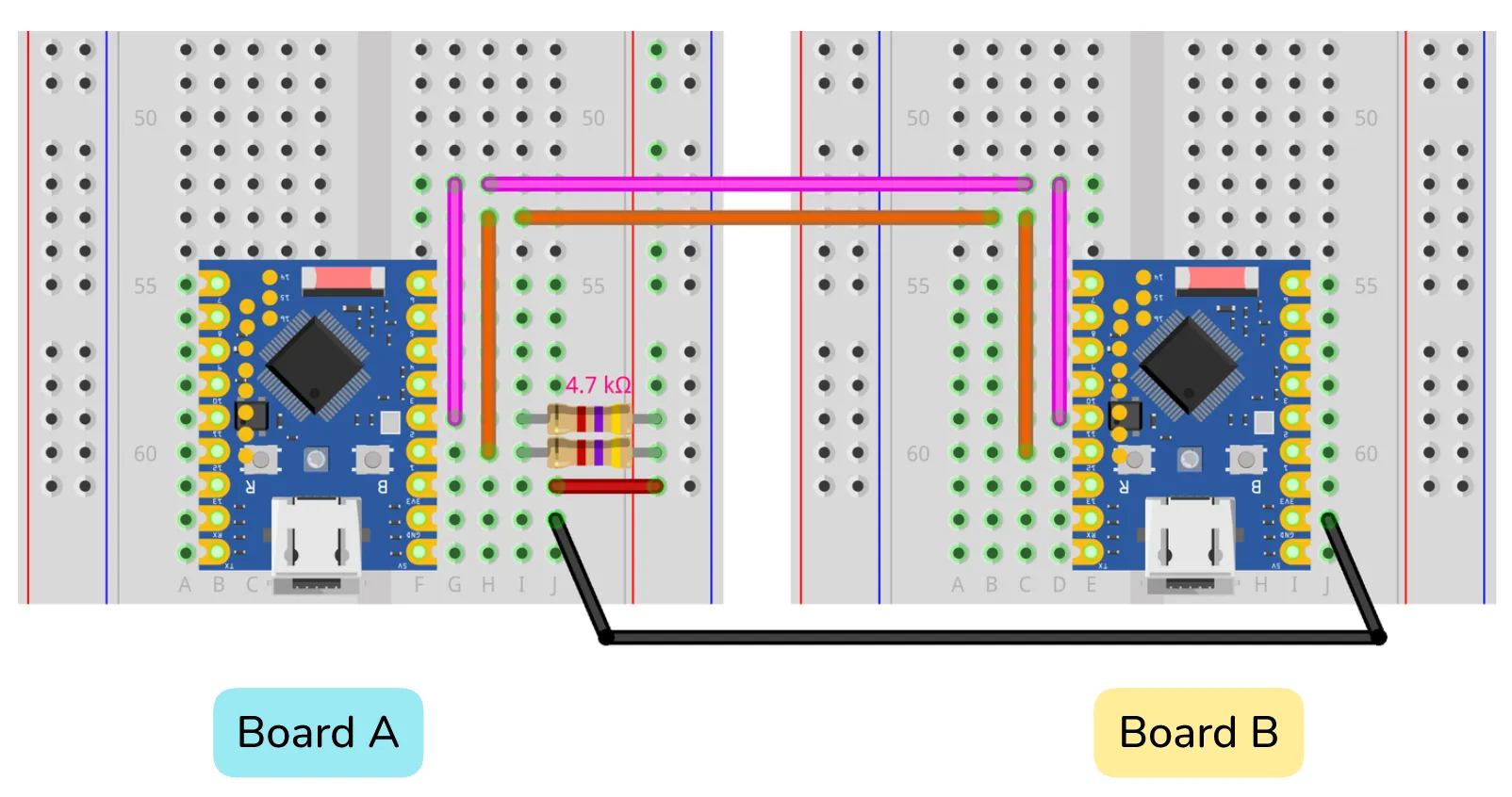
This example also works without an external pull-up resistor. However, in order to ensure the signal stability, it is recommended to connect a pull-up resistor (3.3V can be taken from any development board):
Connect one end of one 4.7kΩ resistor to the SDA wire (i.e., the one that connects GPIO 1 and GPIO 12) and the other end to 3.3V.
Connect one end of the other 4.7kΩ resistor to the SCL wire (i.e., the one that connects GPIO 2 and GPIO 11) and the other end to 3.3V.
| Master device (Board A) | Slave device (Board B) | Description |
|---|---|---|
| GPIO 1 (SDA) | GPIO 12 (SDA) | SDA set in the code |
| GPIO 2 (SCL) | GPIO 11 (SCL) | SCL set in the code |
| GND | GND | Common ground line |
4.2 Example 3: Master Device Requests Data, Slave Device Sends
4.2.1 Master Device Code
#include <Wire.h>

#define SDA 1  // Define the SDA pin
#define SCL 2  // Define the SCL pin

void setup() {
  Serial.begin(9600);

  Wire.begin(SDA, SCL, 100000);  // Initialize the I2C master at 100 kHz
}

void loop() {
  int dataLength = Wire.requestFrom(8, 5);  // Requesting 5 bytes from the slave device with address 8 returns the number of bytes actually received

  Serial.print("Received " + String(dataLength) + " Characters: ");

  while (Wire.available()) {  // Read the received data one by one
    char c = Wire.read();
    Serial.print(c);
  }

  Serial.println();
  delay(500);
}
4.2.2 Slave Device Code
#include <Wire.h>

#define SDA 12  // Define the SDA pin
#define SCL 11  // Define the SCL pin

void setup() {
  Wire.begin(8, SDA, SCL, 100000);  // Initialize the I2C slave device at address 8 and frequency 100 kHz
  Wire.onRequest(requestEvent);     // Register the callback function for the request event
}

void loop() {
  delay(100);
}

// This function is called automatically when the master device requests data
void requestEvent() {
  Wire.write((const uint8_t*)"hello", 5);  // Send 5 bytes containing "hello" to the master device
}
4.2.3 Code Analysis
Master Device Code
#define SDA 1/#define SCL 2: Use macro definitions to specify the GPIO 1 and GPIO 2 for the SDA and SCL lines of I2C.Wire.begin(SDA, SCL, 100000): Initializes the I2C bus.SDA,SCL: Assigns I2C functionality to specified pins.100000: Sets the I2C clock frequency to 100kHz (standard mode). The ESP32 supports standard mode (100kHz), fast mode (400kHz), and higher frequencies (theoretically up to 1MHz, but it depends on the hardware and wiring quality).
int dataLength = Wire.requestFrom(8, 5): This is the core operation of the master device.- It requests
5bytes of data from the slave device at I2C address8. - The function returns the number of bytes actually sent by the slave device and stores it in the
dataLengthvariable.
- It requests
while (Wire.available()): Check if there is still data readable in the I2C receive buffer.char c = Wire.read(): Read a byte from the buffer for printing to the serial monitor.
Slave Device Code
-
#define SDA 12/#define SCL 11: Specifies GPIO 12 and GPIO 11 for the I2C of the slave device. -
Wire.begin(8, SDA, SCL, 100000): Initializes the I2C bus and configures it as a slave device.- The first parameter
8is the I2C address of this slave device. Providing an I2C address (such as the8here) initializes the device to slave mode, while omitting that address defaults to master mode. - Subsequent parameters specify the pin and clock frequency.
- The first parameter
-
Wire.onRequest(requestEvent): This is the key to the slave device. It registers a callback functionrequestEvent. When the master device initiates a data request to this slave device address (8) (i.e., callsrequestFrom), therequestEventfunction will be executed automatically. -
requestEvent()function: Called when the main device requests data.-
Wire.write((const uint8_t*)"hello", 5): Inside this function, we useWire.write()to prepare the data to be sent to the master device. According to the official documentation, this function mainly has two forms of use (i.e., function overloading):write(uint8_t data): Used to send a single byte.write(const uint8_t *data, size_t size): Used to send a data block (or byte array).
-
In the code
Wire.write((const uint8_t*)"hello", 5);, the second form is used to send multiple bytes at once.- First parameter:
(const uint8_t*)"hello"- This is the data to be sent.
"hello"is a string literal, its type isconst char*(a pointer to a constant character). - Since the parameter type required by the function is
const uint8_t*(a pointer to an unsigned byte), we used(const uint8_t*)for forced type casting to match the function's requirements. This is standard practice when handling the underlying byte stream.
- This is the data to be sent.
- Second parameter:
5- This specifies the length of the data we want to send. The string "hello" contains 5 characters, so we tell the function to send 5 bytes.
- First parameter:
-
4.2.4 Running Results
-
Prepare two ESP32 development boards and connect them correctly according to the circuit diagram.
-
Upload the Master Device Code and Slave Device Code to the two development boards respectively.
-
Connect the master device to the computer using a USB cable, and open the serial monitor window to select the correct COM port and baud rate (9600).
-
The following phenomena can be observed at this time:
-
The serial monitor of the master device will print every 500 milliseconds:
Received 5 Characters: hello
-
This indicates that the master device has successfully requested and received data from the slave device at the specified address via the I2C bus.
4.3 Example 4: Master Device Writes Data, Slave Device Reads
4.3.1 Master Device Code
#include <Wire.h>

#define SDA 1  // Define the SDA pin
#define SCL 2  // Define the SCL pin

byte x = 0;  // Define a counter variable

void setup() {
  Wire.begin(SDA, SCL, 100000);  // Initialize the I2C master at 100kHz
}

void loop() {
  Wire.beginTransmission(8);               // Start sending data to the slave device at address 8
  Wire.write((const uint8_t*)"x is ", 5);  // Send the string "x is " (5 bytes)
  Wire.write(x);                           // Send the number x
  Wire.endTransmission();                  // End the transmission

  x++;         // The counter increments
  delay(500);  // Delay 500 milliseconds
}
4.3.2 Slave Device Code
#include <Wire.h>

#define SDA 12  // Define the SDA pin
#define SCL 11  // Define the SCL pin

void setup() {
  Wire.begin(8, SDA, SCL, 100000);  // Initialize the I2C slave device at address 8 and frequency 100kHz
  Wire.onReceive(receiveEvent);     // Register the callback function for the receive event
  Serial.begin(9600);                // Initialize serial communication
}

void loop() {
  delay(100);
}

// This function is called automatically when master device data is received
void receiveEvent(int len) {
  while (Wire.available() > 1) {  // Read all data except the last byte (string part)
    char c = Wire.read();
    Serial.print(c);
  }
  int x = Wire.read();  // Read the last byte (number)
  Serial.println(x);    // Print numbers on a new line
}
4.3.3 Code Analysis
Master Device Code
- **
byte x = 0; '**: Define a variable of typex` and initialize to 0 for counting. Wire.beginTransmission(8): Prepare to start sending data to the device at address8.Wire.write(...): Put the data into the send buffer. Here we put the value of the string "x is" and the variablex. The data has not been sent yet.Wire.endTransmission(): Send all data in the buffer through the I2C bus at once and end the current communication.x++: Increments the value ofxby one in each loop.
Slave Device Code
Wire.onReceive(receiveEvent): Registers the callback functionreceiveEventfor the receive event. This function is automatically executed when the master device completes a transfer (callingendTransmission()).receiveEvent(int len): This function automatically receives an integer parameter when called, which indicates the total number of data bytes transmitted by the master device this time. The design of theWirelibrary requires the callback functiononReceiveto accept this integer parameter, as the library will always pass the number of received bytes.- In this code,
Wire.available()is used to determine how much data is left in the buffer, which is a flexible way to handle it. - But in other scenarios,
lenis very useful. For example, you can checkif (len != 6)before reading the data to verify whether the length of the received data meets your protocol expectations, thereby increasing the robustness of your code.
- In this code,
while (Wire.available() > 1):Wire.available()returns the number of bytes readable in the receive buffer. This loop reads and prints characters until only the last byte remains in the buffer.int x = Wire.read(): Reads the last byte left in the buffer. According to the master's code, this byte is the value of the variablex.Serial.println(x): Prints the received numberxto the serial monitor.
4.3.4 Running Results
-
Prepare two ESP32 development boards and connect them correctly according to the circuit diagram.
-
Upload the Master Device Code and Slave Device Code to the two development boards respectively.
-
Connect the slave device to the computer using a USB cable, and open the serial monitor window to select the correct COM port and baud rate (9600).
-
The following phenomena can be observed at this time:
-
The serial monitor from the slave device receives data every 500 milliseconds and prints it out in increments like this:
x is 0x is 1x is 2x is 3x is 4And the number will keep increasing until the variable
xof typebyteoverflows and starts over from 0 (0-255).
-
This indicates that the master device successfully sent a data packet combining a string and a variable to the slave device, and the slave device was able to correctly receive, parse, and display it.