SPI Communication
The core logic of this tutorial applies to all ESP32 boards, but all the operation steps are explained using the example of the Waveshare ESP32-S3-Zero mini development board. If you are using a development board of another model, please modify the corresponding settings according to the actual situation.
SPI (Serial Peripheral Interface) is a high-speed, full-duplex synchronous serial communication protocol. SPI is widely used for communication between microcontrollers and various peripherals such as TF cards, displays, sensors, Flash memory, etc.
SPI has the following features:
- Four-wire communication: Communicates using 4 signal lines (can be reduced to 3 when a single slave device is used)
- Master-slave architecture: A clear master-slave relationship, where the master device controls the communication timing
- Full-duplex: Data can be sent and received simultaneously
- High-speed transmission: The speed is usually faster than I2C and UART, reaching tens of MHz
- Synchronous communication: The master device provides the clock signal, ensuring reliable data transmission
The four core signal lines of the SPI protocol are:

- SCK (Serial Clock Line): Serial clock line. The clock signal generated by the master is used to synchronize data transmission.
- MOSI (Master Out Slave In): Master Out Slave In line. The master device sends data to the slave device through this line.
- MISO (Master In Slave Out): Master In Slave Out line. The slave device sends data to the master device through this line.
- SS/CS (Slave Select/Chip Select): Chip select signal line. The master uses this line to select the slave to communicate with, and the low level is selected. The SPI master selects the target slave through different CS (chip select) lines. Each additional SPI peripheral takes up an additional CS pin.
Supplementary notes on SPI term updates
You may notice that the SPI terms are changing in some new technical manuals or open-source projects. Understanding these new terms will help you read the latest materials without barriers. Here are the correspondences between the old and new terms:
| Category | Traditional term | New term |
|---|---|---|
| Device role | Master | Controller |
| Device role | Slave | Peripheral |
| Signal line | MOSI | PICO (Peripheral In / Controller Out) |
| Signal line | MISO | POCI (Peripheral Out / Controller In) |
1. SPI in ESP32
The ESP32 chip typically has multiple SPI controllers (refer to the target chip's datasheet for the specific number):
- SPI0 and SPI1: used for accessing Flash or PSRAM.
- SPI2 and SPI3: General-purpose SPI controllers available for users to use freely, with flexible pin assignment.
In the Arduino environment, we communicate with peripherals through the SPI.h library. For different models of ESP32s, their SPI bus is accessed in the following way:
- ESP32 (Classic Model)
- ESP32-S3
SPI: Default SPI bus object, corresponding to VSPI (hardware SPI3).SPIClass hspi(HSPI): Creates the second bus object, corresponding to HSPI (hardware SPI2).
In the ESP32-S3 Technical Reference Manual (30.4 SPI Architecture Overview), hardware SPI2 is also known as FSPI. The "F" here stands for "Fast", not "Flash". In Arduino, this SPI2 bus is a fully functional general-purpose bus.
SPI: Default SPI bus object, corresponding to hardware SPI2 (FSPI).SPIClass hspi(HSPI): Creates the second bus object, corresponding to hardware SPI3.
When calling SPI.begin(), if you don't specify a pin, the library will use the default pin for that bus; If a custom pin number is provided, it is routed through the GPIO matrix.
When selecting SPI pins, be careful to avoid pins already occupied by other functions (such as USB, onboard LED). For specific pins, please refer to the schematic or pin diagram of the development board used.
2. Example 1: Control the Display Using SPI
This example demonstrates how to drive an OLED display using the SPI interface. SPI-based displays typically have faster refresh rates compared to I2C.
2.1 Circuit Assembly
Components required:
- Waveshare 1.5inch OLED Module × 1
- Breadboard × 1
- Wire
- ESP32 development board
Connect the circuit according to the wiring diagram below:
ESP32-S3-Zero Pinout Diagram

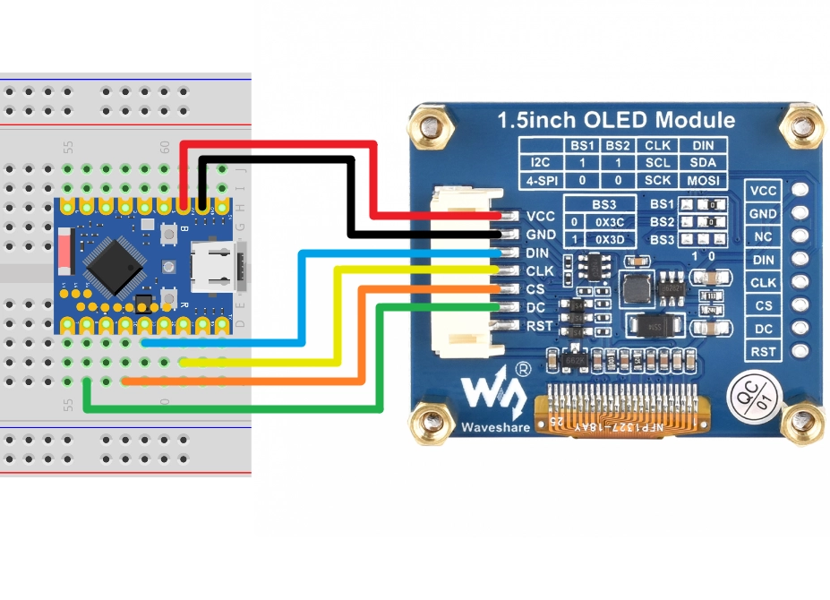
| ESP32 pin | OLED module | Description |
|---|---|---|
| GPIO 13 | SCK | SPI clock line |
| GPIO 11 | MOSI | SPI data output |
| GPIO 10 | CS | Chip select signal |
| GPIO 8 | DC | Data/command select |
| 3.3V | VCC | Power positive terminal |
| GND | GND | Power negative terminal |
2.2 Code
This code example relies on the "Adafruit_SSD1327" library. Please search for and install the 'Adafruit SSD1327' library in the Arduino IDE's library manager.
For installation methods, please refer to: Arduino library manager tutorial.
#include <SPI.h>
#include <Adafruit_SSD1327.h>

#define OLED_SCK 13    // Clock cable
#define OLED_MOSI 11   // Data output line
#define OLED_CS 10     // Chip select line

#define OLED_DC 8      // Data/command select line
#define OLED_RESET -1  // Reset pin (unused)

// Create a display object
Adafruit_SSD1327 display(128, 128, &SPI, OLED_DC, OLED_RESET, OLED_CS);

void setup() {

  Serial.begin(9600);

  // Initialize SPI bus
  SPI.begin(OLED_SCK, -1, OLED_MOSI, OLED_CS);

  Serial.println("SSD1327 OLED test");

  // Initialize the display
  if (!display.begin()) {
    Serial.println("Unable to initialize OLED");
    while (1) yield();
  }

  // Display settings
  display.clearDisplay();
  display.setRotation(3);
  display.setTextSize(2);
  display.setTextColor(SSD1327_WHITE);

  // Display text
  display.setCursor(10, 10);
  display.println("Hello,");
  display.setCursor(40, 30);
  display.setTextColor(SSD1327_BLACK, SSD1327_WHITE);
  display.println(" World!");
  display.display();
  display.setCursor(15, 60);
  display.setTextColor(SSD1327_WHITE);
  display.println("SPI TEST");
  display.display();

  delay(1000);
}

void loop() {
}
2.3 Code Analysis
-
#include <SPI.h>: Includes Arduino's SPI communication library. -
SPI.begin(OLED_SCK, -1, OLED_MOSI, OLED_CS): Initializes the SPI bus and specifies the pins.OLED_SCK: Clock line pin-1: MISO pin (not used here, as the display only requires one-way data transmission)OLED_MOSI: Data output line pinOLED_CS: Chip select pin
-
Adafruit_SSD1327 display(...): Creates a display object.128, 128: Screen resolution&SPI: Use the default SPI objectOLED_DC: Data/command select pinOLED_RESET: Reset pinOLED_CS: Chip select pin
-
The role of DC pins: SPI displays often require additional DC (Data/Command) pins to distinguish whether the transmission is display data or control commands.
2.4 Running Results
-
The OLED screen will light up and display the following:
- The first line is "Hello," in white font.
- The second line is the inverted color display "World!" (i.e. black text with white background).
- The third line is "SPI TEST" in white font.
3. Example 2: Use Multiple SPI Devices
Code
In the SPI library, the object SPI is already pre-created. If you want to use another SPI controller, you can define it as follows:
#include <SPI.h>

SPIClass hspi(HSPI);

void setup() {

  // Initialize the HSPI bus and specify its pins
  hspi.begin(HSPI_SCLK, HSPI_MISO, HSPI_MOSI, HSPI_CS);

  // ...
}

void loop() {
  // ...
}
4. Related Links
- SPI | Arduino-ESP32 documentation
- Arduino & Serial Peripheral Interface (SPI) | Arduino Documentation
- SPI | Arduino Documentation
- GPIO Matrix and Pin Mux | Arduino-ESP32 documentation
- A Resolution to Redefine SPI Signal Names | OSHWA
- New SPI Terminology | OSHWA
- ESP32 Series SPI Naming Pattern (GitHub Issue)