Working with Jetson Orin
This module is designed based on the Jetson Orin form factor, allowing users to directly assemble it onto the Jetson Orin Nano/NX Developer Kits.
Hardware Connection
|
|
|
-
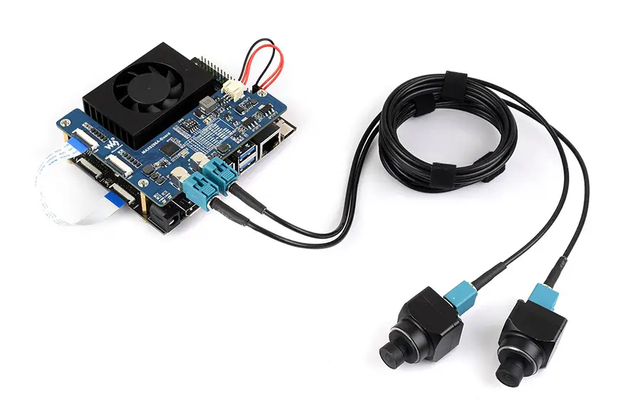
As shown in the diagram, connect the CSI0 interface of the deserializer board to the CAM1 interface of the Jetson Orin mainboard using the supplied cable.
CSI Interface CompatibilityThe CSI pin definitions of the CAM0 and CAM1 interfaces on the NVIDIA Jetson® Orin™ Nano kit are different. Currently, the deserializer board can only be connected to the CAM1 interface on the official carrier board. Please refer to the relevant pin definitions and the CAM0/1 interface pinout in the Jetson® Orin™ kit schematic.
FPC Cable Length LimitationThe 22PIN FPC cable does not have precise impedance control. When using high-resolution cameras, the CSI data rate is high. It is recommended to use short FPC cables:
- Two 8MP cameras connected simultaneously: tested to work only with a 5 cm cable.
- Single-camera connection: 10 cm or 15 cm cables can be used.
-
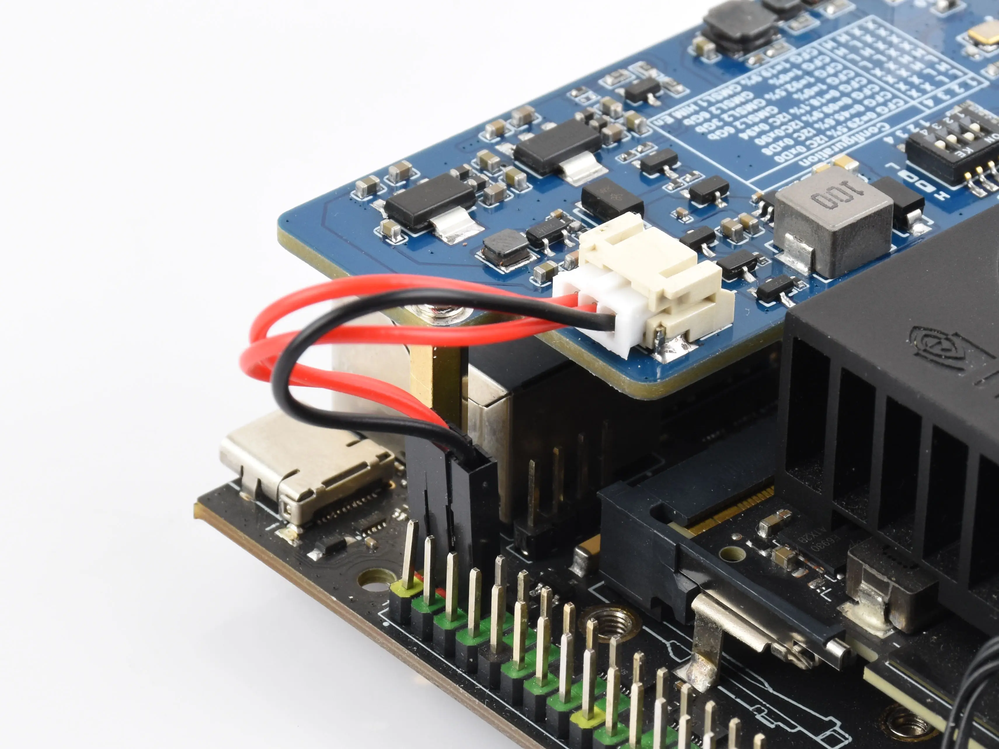
Connect the power cable to the power connector of the deserializer board and to the 5 V and GND pins on the 40PIN header of the Jetson Orin mainboard. To ensure the deserializer board receives sufficient power, please connect both 5V pins. External power supply can also be connected
-
Connect the GMSL camera to the camera interface on the deserializer board using a coaxial cable.
-
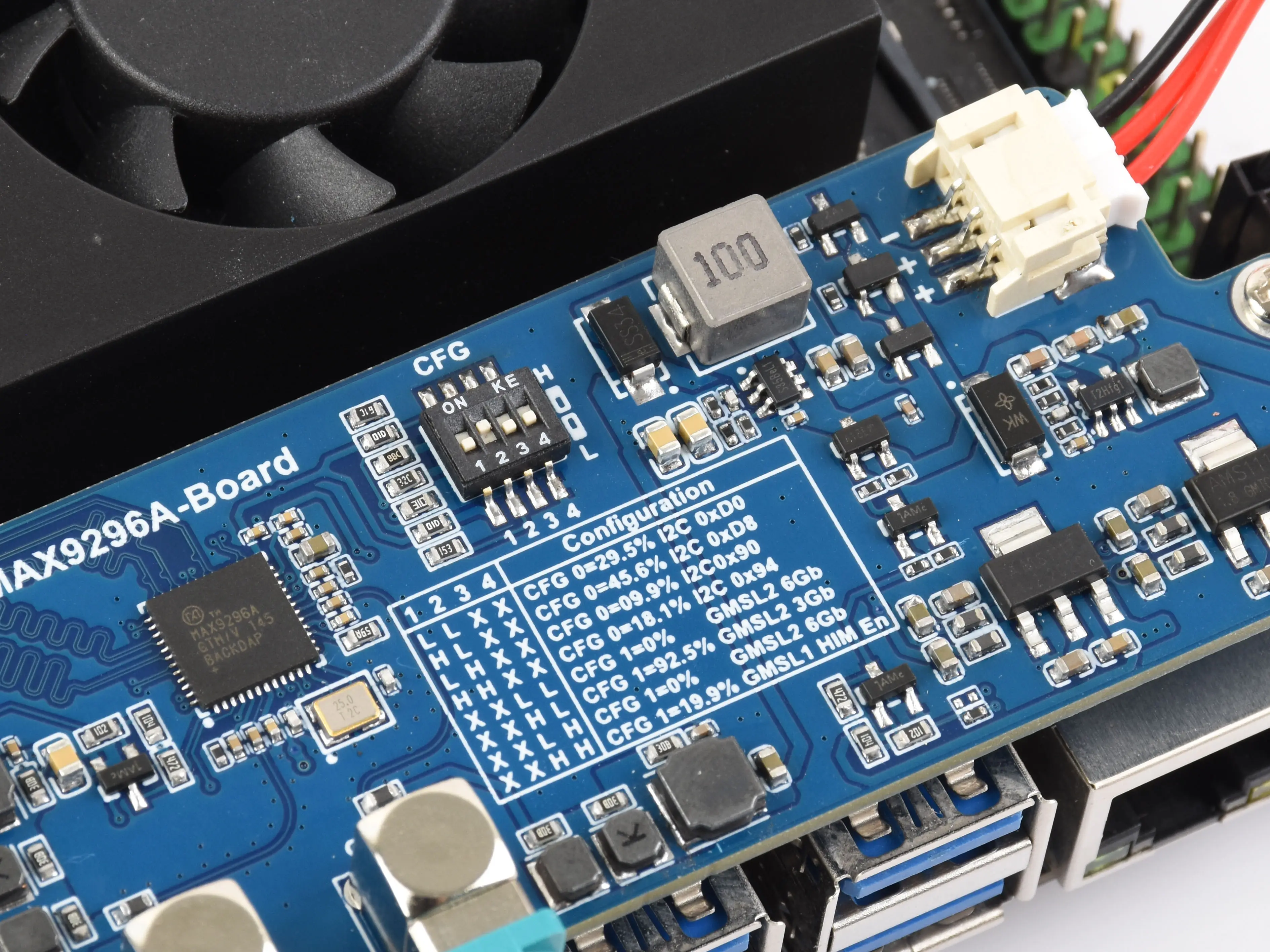
Set the CFG switch to the '0100' position as shown in the diagram (default configuration for ISX031 camera)
- The default power-on I2C address and CFG settings configured by the switch are overwritten by the SerDes software configuration commands after power-on, so no special switch operation is required.
Software Configuration
Newer Image Versions
-
The newer version driver supports the latest R36.5.0 image. Currently, it only supports the Jetson Orin Nano (Orin NX support is pending).
-
Check the current system version with the following command to ensure it is supported.
cat /etc/nv_tegra_release -
After powering on the mainboard, open a Terminal, download the driver package, and extract it:
wget https://files.waveshare.com/wiki/MAX9296-GMSL-Deser-Module/MAX9296-GMSL-DESER-MODULE.zipunzip MAX9296-GMSL-DESER-MODULE.zip -
Use the
cdcommand to enter the driver package directory and copy the driver files to the appropriate paths.cd MAX9296-GMSL-DESER-MODULEsudo cp dtbo/*.dtbo /boot/sudo cp ko/*.ko /usr/lib/modules/5.15.185-tegra/updates/drivers/media/i2c/sudo depmod -
Configure the driver using the Jetson-IO tool:
sudo /opt/nvidia/jetson-io/jetson-io.py -
Select the corresponding camera driver based on the connected camera:
Jetson Expansion Header Tool└── Configure Jetson 22pin CSI Connector└── Configure for compatible hardware├── GMSL-1MP-Camera-A├── GMSL-2MP-Camera-A├── ISX031C-GMSL-Camera-A└── ISX031C-GMSL-Camera-B -
Save the configuration and reboot the system.
Older Image Versions
-
The Jetson Orin mainboard needs to be flashed with a corresponding supported Jetson system. Currently, the driver only supports version R35.4.1.
-
You can check the current system version using the command:
cat /etc/nv_tegra_release
-
-
After powering on the mainboard, open a Terminal, download the driver package, and extract it:
wget https://files.waveshare.com/wiki/MAX9296-GMSL-Camera-Board/MAX9296-GMSL-Camera-Board-Driver.zipunzip MAX9296-GMSL-Camera-Board-Driver.zip -
Use the
cdcommand to enter the driver package directory and list the files-
Enter the corresponding directory based on the camera model used. Here we use ISX031 as an example
cd MAX9296-GMSL-Camera-Board-Driverlscd ONXA_SY.ISX031Fx2_L4TR35.4.1cd kernel
-
-
In the kernel files, the dtb folder contains device tree files supporting multiple mainboard models. We need to use the device tree file that matches the current mainboard model
-
First, you can use the command
sudo dmesg | grep kernelto check the device tree currently used by the mainboard -
For example, if the queried device tree file is
tegra234-p3767-0004-p3768-0000-a0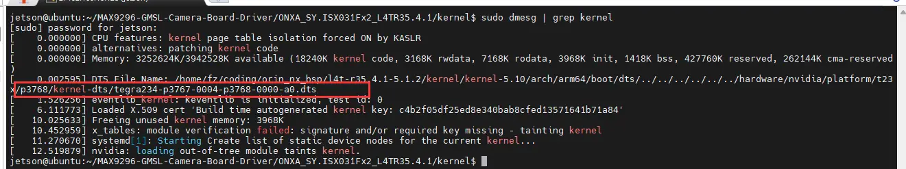
-
-
Copy the dtb file and Image file of the same model from the driver to the mainboard's
/bootdirectorysudo cp dtb/tegra234-p3767-0004-p3768-0000-a0.dtb /bootsudo cp Image /boot -
After copying the files, modify the device tree file specified for boot in
extlinux.conf-
Duplicate and add another boot label, change the FDT file path within it to the directory of the copied file, and set the new added label as the default boot option
Important NoteWhen modifying the boot configuration file, double-check everything. Save the changes only after confirming correctness, then reboot the system. An incorrect configuration may prevent the system from booting properly!
sudo vi /boot/extlinux/extlinux.conf -
In the vi editor, press i to enter edit mode, and press esc to exit edit mode. After exiting edit mode, you can type
:wq!to save the file and quit.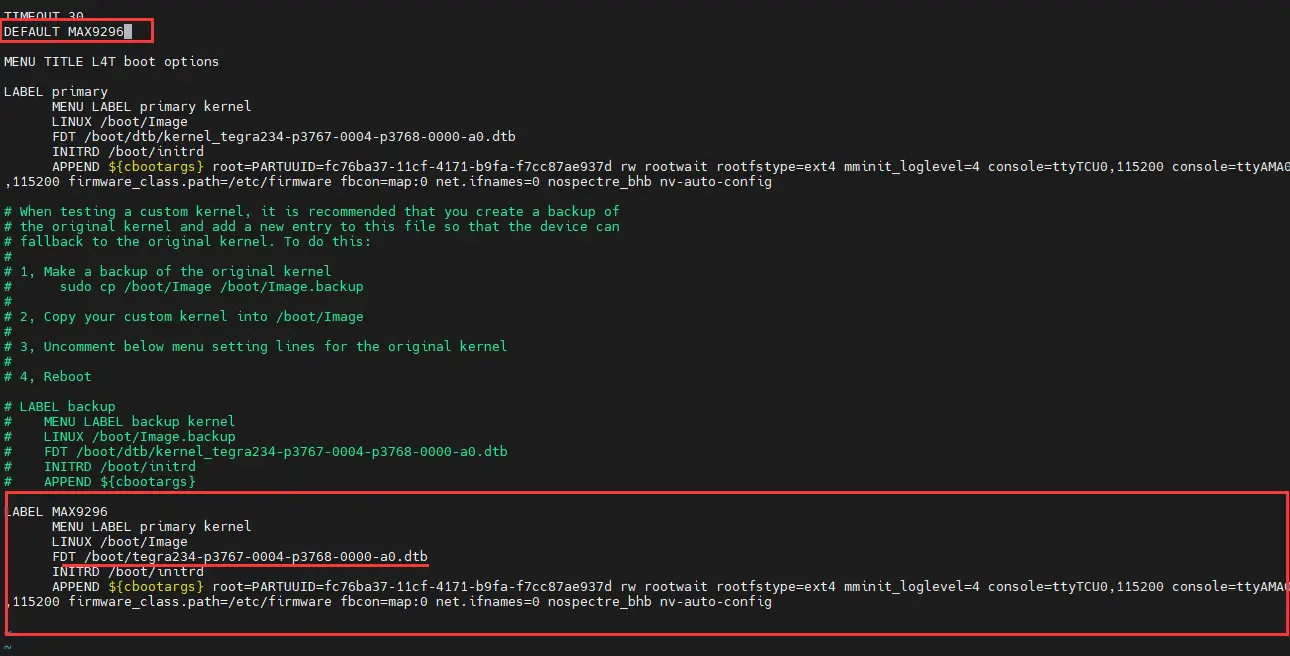
-
-
After saving the file, reboot the system
Quick Test
Check if the Camera is Properly Recognized
sudo dmesg | grep connected
If it returns a message like /dev/video2 is connected, it indicates the camera has been properly detected.
Install GStreamer
sudo apt install \
    nvidia-l4t-gstreamer \
    gstreamer1.0-plugins-bad \
    gstreamer1.0-plugins-good \
    gstreamer1.0-plugins-base \
    gstreamer1.0-tools
Preview the Camera Feed
-
You can use the following command to perform a preview test of the camera.
- The preview test requires an HDMI or DP display to be connected. Please ensure the screen is properly connected and displaying.
- Note: Change the video device number to the one indicated in the previous detection step.
- Note: Modify the command parameters according to the resolution supported by the camera.
-
GMSL-1MP-Camera-A
gst-launch-1.0 v4l2src device=/dev/video0 ! "video/x-raw, format=(string)UYVY, width=(int)1280, height=(int)960" ! fpsdisplaysink video-sink=xvimagesink sync=falsegst-launch-1.0 v4l2src device=/dev/video1 ! "video/x-raw, format=(string)UYVY, width=(int)1280, height=(int)960" ! fpsdisplaysink video-sink=xvimagesink sync=false -
GMSL-2MP-Camera-A
gst-launch-1.0 v4l2src device=/dev/video0 ! "video/x-raw, format=(string)UYVY, width=(int)1920, height=(int)1080" ! fpsdisplaysink video-sink=xvimagesink sync=falsegst-launch-1.0 v4l2src device=/dev/video1 ! "video/x-raw, format=(string)UYVY, width=(int)1920, height=(int)1080" ! fpsdisplaysink video-sink=xvimagesink sync=false -
ISX031C-GMSL-Camera-A
gst-launch-1.0 v4l2src device=/dev/video0 ! "video/x-raw, format=(string)UYVY, width=(int)1920, height=(int)1536" ! fpsdisplaysink video-sink=xvimagesink sync=falsegst-launch-1.0 v4l2src device=/dev/video1 ! "video/x-raw, format=(string)UYVY, width=(int)1920, height=(int)1536" ! fpsdisplaysink video-sink=xvimagesink sync=false -
ISX031C-GMSL-Camera-B
gst-launch-1.0 v4l2src device=/dev/video0 ! "video/x-raw, format=(string)UYVY, width=(int)1920, height=(int)1536" ! fpsdisplaysink video-sink=xvimagesink sync=falsegst-launch-1.0 v4l2src device=/dev/video1 ! "video/x-raw, format=(string)UYVY, width=(int)1920, height=(int)1536" ! fpsdisplaysink video-sink=xvimagesink sync=false