Working with Arduino
This chapter contains the following sections. Please read as needed:
New to Arduino ESP32 development and looking for a quick start? We have prepared a comprehensive Getting Started Tutorial for you.
- Section 0: Getting to Know ESP32
- Section 1: Installing and Configuring Arduino IDE
- Section 2: Arduino Basics
- Section 3: Digital Output/Input
- Section 4: Analog Input
- Section 5: Pulse Width Modulation (PWM)
- Section 6: Serial Communication (UART)
- Section 7: I2C Communication
- Section 8: SPI Communication
- Section 9: Wi-Fi Basics
- Section 10: Web Server
- Section 11: Bluetooth
- Section 12: LVGL GUI Development
- Section 13: Comprehensive Project
Note: This tutorial uses the ESP32-S3-Zero as a reference example, and all hardware code is based on its pinout. Before you start, we recommend checking the pinout of your development board to ensure the pin configuration is correct.
Arduino Getting Started
Setting Up Development Environment
1. Installing and Configuring Arduino IDE
For the ESP32-C6-Touch-AMOLED-1.43 development board, the Arduino IDE requires the installation of arduino-esp32 core library version v3.3.0 or later.
Please refer to the tutorial Installing and Configuring Arduino IDE Tutorial to download and install the Arduino IDE and add ESP32 support.
2. Installing Libraries
- When installing Arduino libraries, there are typically two methods: Online Installation and Offline Installation. If the library installation requires offline installation, you must use the provided library file.
- For most libraries, users can easily search and install them through the online Library Manager in the Arduino software. However, some open-source libraries or custom libraries are not synchronized to the Arduino Library Manager, so they cannot be acquired through online searches. In this case, users can only manually install these libraries offline.
- The sample program package for the ESP32-C6-Touch-AMOLED-1.43 development board can be downloaded from here. The
Arduino\librariesdirectory within the package already includes all the library files required for this tutorial.
| Library/File Name | Description | Version | Installation Method |
|---|---|---|---|
| LVGL | Graphical library | v8.3.11/v9.3.0 | "Install Offline" |
| SensorLib | Sensor control library | v0.3.1 | "Install Online" or "Install Offline" |
There are strong dependencies between versions of LVGL and its driver libraries. For example, a driver written for LVGL v8 may not be compatible with LVGL v9. To ensure stable reproduction of the examples, it is recommended to use the specific versions listed in the table above. Mixing different library versions may cause compilation failures or runtime exceptions.
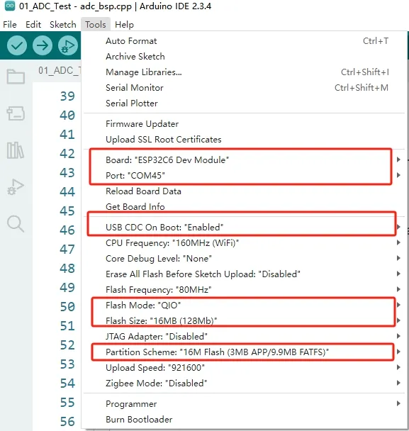
3. Arduino Project Parameter Settings
Example
The Arduino examples are located in the Arduino/examples directory of the example package.
| Demo | Basic Program Description | Dependency Library |
|---|---|---|
| 01_ADC_Test | Get the voltage value of the lithium battery | - |
| 02_I2C_PCF85063 | Print real-time time of RTC chip | SensorLib |
| 03_I2C_QMI8658 | Print the raw data from IMU | SensorLib |
| 04_SD_Card | Load and display the information of the TF card | - |
| 05_WIFI_AP | Set to AP mode to obtain the IP address of the access device | - |
| 06_WIFI_STA | Set to STA mode to connect to WiFi and obtain an IP address | - |
| 07_BATT_PWR_Test | Control power via the PWR button when powered solely by the lithium battery | - |
| 08_Audio_Test | Play the sound recorded by the microphone through the speaker | - |
| 09_LVGL_V8_Test | LVGLV9 demo | LVGL V8.3.11 |
| 10_LVGL_V9_Test | LVGLV8 demo | LVGL V9.3.0 |
| 11_FactoryProgram | Comprehensive demo | LVGL V8.3.11 |
01_ADC_Test
Description
- The analog voltage connected through the GPIO is converted to digital by the ADC, and then the actual lithium battery voltage is calculated and printed to the terminal.
Hardware Connection
- Connect the board to the computer using a USB cable
Code Analysis
adc_bsp_init(void): Initializes ADC1, including creating an ADC one-shot trigger unit and configuring Channel 0 of ADC1.adc_get_value(float *value,int *data): Reads the value from Channel 0 of ADC1, calculates the corresponding voltage based on the reference voltage and resolution, and stores it at the location pointed to by the passed pointer. Stores 0 if the read fails.adc_example(void* parameter): After initializing ADC1, creates an ADC task. This task reads the ADC value every second and calculates the system voltage from the raw ADC reading.
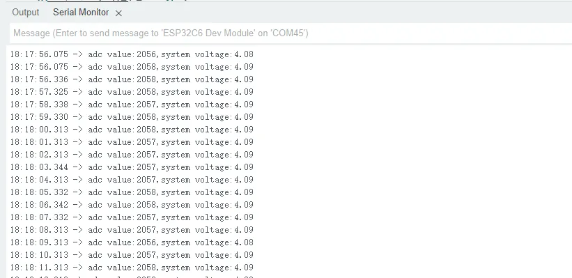
Operation Result
-
After the program is compiled and downloaded, you can view the printed ADC values and voltage output by opening the Serial Monitor, as shown in the following image:
02_I2C_PCF85063
Description
- Through the I2C protocol, initialize the PCF85063 chip, set the time, and then periodically read the time and print it to the terminal
Hardware Connection
- Connect the board to the computer using a USB cable
Code Analysis
void i2c_rtc_loop_task(void *arg): Creates an RTC task to implement the RTC function, reading the clock of the RTC chip every second and outputting it to the terminal.
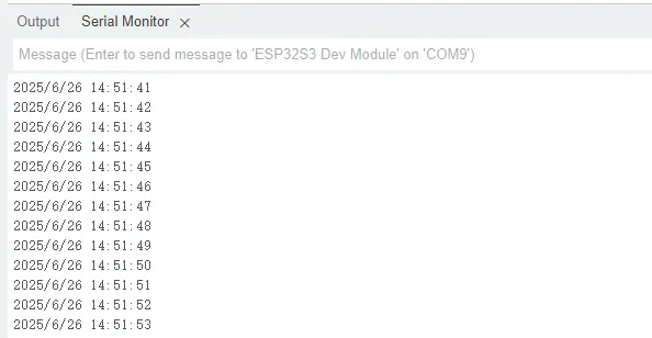
Operation Result
-
Open the serial port monitoring, you can see the RTC time of the printout, as shown in the figure below:
03_I2C_QMI8658
Description
- Initialize the QMI8658 chip via the I2C protocol, then read the corresponding attitude information every 200ms and print it to the terminal.
Hardware Connection
- Connect the board to the computer using a USB cable
Code Analysis
void i2c_qmi_loop_task(void *arg): Creates a QMI task to acquire attitude information. The task reads and prints accelerometer and gyroscope data at 200ms intervals, and outputs the results to the serial console.
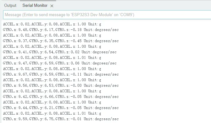
Operation Result
-
Open the serial monitor to view the raw data output from the IMU (Euler angles require conversion), as shown in the figure below:
04_SD_Card
Description
- Drive the TF card via SDSPI mode. After successful mounting, print the TF card information to the terminal.
Hardware Connection
- Install a FatFs-formatted into the board before powering on
Code Analysis
sdcard_init(void): Initializes the TF card using SDSPI mode.loop(): Tests TF card read/write functions. You need to uncomment the#define sdcard_write_Testmacro definition.
//#define sdcard_write_Test
Operation Result
-
Click to open the Serial Monitor device. You can see the output TF card information; practical_size indicates the actual capacity of the TF card, as shown below:

05_WIFI_AP
Description
- This demo can set the development board as a hotspot, allowing phones or other devices in STA mode to connect to the development board.
Hardware Connection
- Connect the board to the computer using a USB cable
Code Analysis
-
In the
05_WIFI_AP.inofile, locatessidandpassword. Phones or other STA mode devices can then connect to the board using this SSID and password.const char *ssid = "ESP32_AP";const char *password = "12345678";
Operation Result
-
After flashing the program, open the serial terminal. If the device is successfully connected to the hotspot, the MAC address of the device will be output, as shown in the figure:

06_WIFI_STA
Description
- This example can configure the development board as a STA device to connect to a router, thereby enabling access to the system network.
Hardware Connection
- Connect the board to the computer using a USB cable
Code Analysis
-
In the
06_WIFI_STA.inofile, locatessidandpassword, and modify them to match the SSID and Password of an available router in your current environment.const char *ssid = "you_ssid";const char *password = "you_password";
Operation Result
-
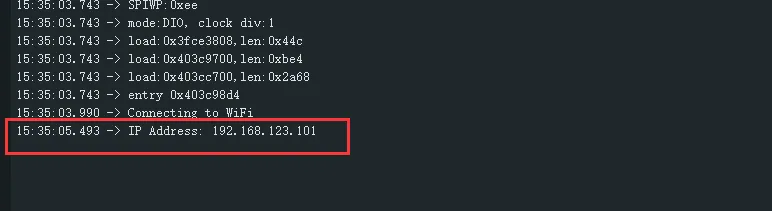
After flashing the program, open the serial terminal, if the device is successfully connected to the hotspot, the IP address obtained will be output, as shown in the figure:
07_BATT_PWR_Test
Description
- Demonstrates how to control the system power via the PWR button when powered by the lithium battery.
Hardware Connection
- Power the development board with a lithium battery.
Code Analysis
setup_ui(lv_ui *ui): Initializes the UI interface for visual control.esp_io_expander_new_i2c_tca9554(): Initializes the lithium battery control IO port.user_button_init(): Initializes the buttons and their trigger events.example_button_task(void* parameter): Task waiting for button event triggers.
Operation Result
-
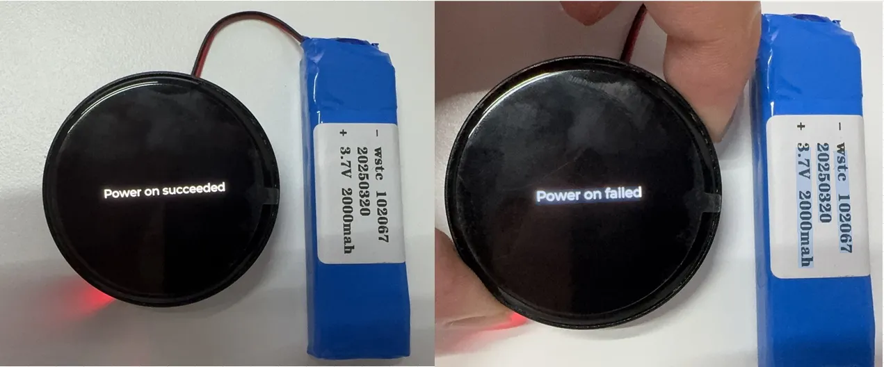
After the program is flashed, disconnect the USB power supply and connect the lithium battery. Power on by pressing and holding the PWR button, as shown in the figure:
 tip
tip- Press and hold the PWR button, wait until the screen displays "Power on succeeded", indicating successful power-on, then release the button.
- Press and hold the PWR button again, wait until the screen displays "Power on failed", indicating successful power-off, then release the button.
08_Audio_Test
Description
- Demonstrates how to get data from the microphone and then play it through the speaker
Hardware Connection
- Connect the board to the computer using a USB cable
- Connect the speaker to the onboard MX1.25 2PIN speaker interface.
Code Analysis
i2c_master_Init(): Initializes the I2C bus.esp_io_expander_new_i2c_tca9554(): Initializes the amplifier CTRL control IO port.esp_codec_dev_set_out_vol(): Sets the output volume during playback.esp_codec_dev_set_in_gain(): Sets the input gain for recording.
Operation Result
-
After the program is flashed, speak into the microphone, and the speaker will automatically play back the recorded sound. This example has no UI display.
tip- If you find the playback volume to be too low, prioritize using "esp_codec_dev_set_out_vol" to increase the playback volume
- If the sound is still not loud enough after increasing the playback volume, you can use "esp_codec_dev_set_in_gain" to increase the gain during recording
09_LVGL_V8_Test
Description
- Implements various multifunctional GUI interfaces on the screen by porting LVGL V8.
Hardware Connection
- Connect the board to the computer using a USB cable
Code Analysis
-
If you need to rotate the display by 90 degrees, locate the
#define EXAMPLE_Rotate_90macro definition in theuser_config.hfile and uncomment it. -
If you need to perform a backlight test, locate the
#define Backlight_Testingmacro definition in theuser_config.hfile and uncomment it.//#define Backlight_Testing//#define EXAMPLE_Rotate_90
Operation Result
-
After the program is flashed, the device operation result is as follows:

10_LVGL_V9_Test
Description
- Implements various multifunctional GUI interfaces on the screen by porting LVGL V9.
Hardware Connection
- Connect the board to the computer using a USB cable
Code Analysis
-
If you need to rotate the display by 90 degrees, locate the
#define EXAMPLE_Rotate_90macro definition in theuser_config.hfile and uncomment it. -
If you need to perform a backlight test, locate the
#define Backlight_Testingmacro definition in theuser_config.hfile and uncomment it.//#define Backlight_Testing//#define EXAMPLE_Rotate_90
Operation Result
-
After the program is flashed, the device operation result is as follows:
11_FactoryProgram
Description
- Comprehensive project, you can simply test the onboard hardware functions, or directly use the BIN firmware we provide for flashing.
Hardware Connection
- Connect the board to the computer using a USB cable
Code Analysis
ContsGroups = xEventGroupCreate();            // Create an event group for task synchronization
 Serial.begin(115200);                // Initialize serial communication, baud rate 115200
 Tca9554_Init();                               // Initialize the TCA9554 GPIO expander chip
 display = new DisplayPort(i2cbus, 466, 466);  // Create a display port instance, resolution 466x466
 display->DisplayPort_TouchInit();             // Initialize the display touch function
 Lvgl_PortInit(*display);                      // Initialize the LVGL graphics library port
 Adc_PortInit();                               // Initialize the ADC port
 Custom_ButtonInit();                          // Initialize custom buttons
 I2cRtcSetup(&i2cbus, 0x51);                  // Initialize the I2C RTC clock chip, address 0x51
 Set_I2cRtcTime(2026, 1, 1, 0, 0, 0);          // Set RTC time to 2026-01-01 00:00:00
 I2cQmiSetup(&i2cbus, 0x6b);                   // Initialize the I2C IMU sensor, address 0x6b
 codecport = new CodecPort(i2cbus,"C6_AMOLED_1_43"); // Create an audio codec port instance
Operation Result
-
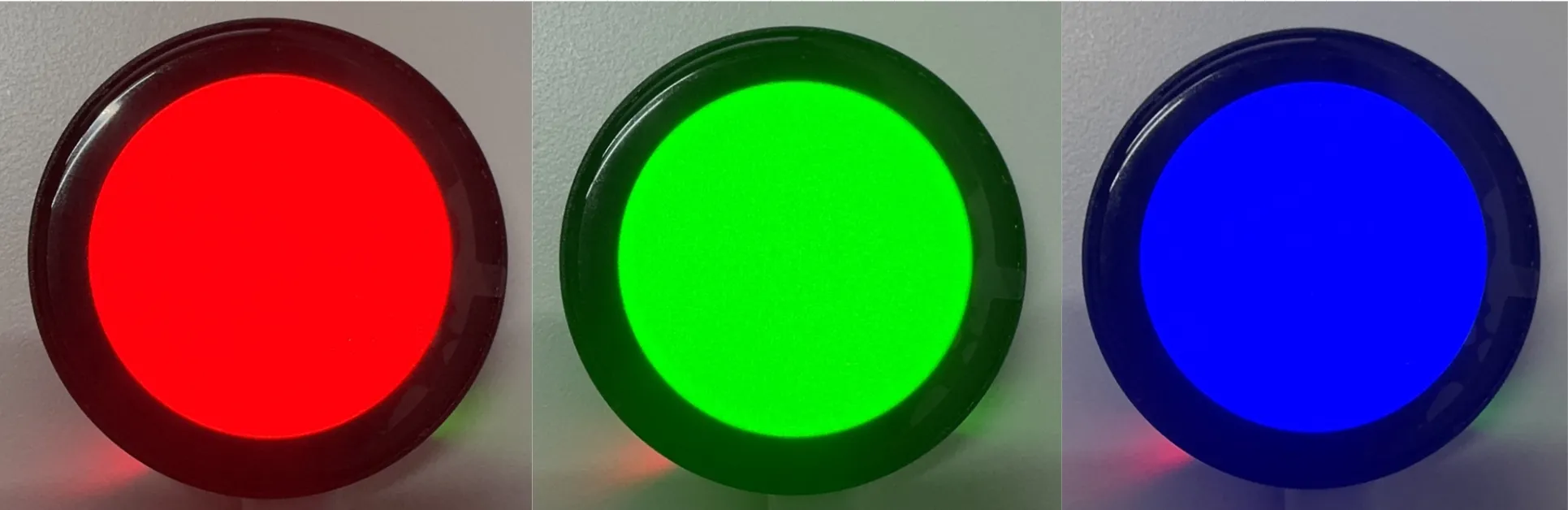
The display cycles through red, green, and blue colors (transition interval 1.5 seconds), as shown:
-
After the system finishes displaying the above colors, it will automatically enter the onboard hardware information interface, as shown in the figure:
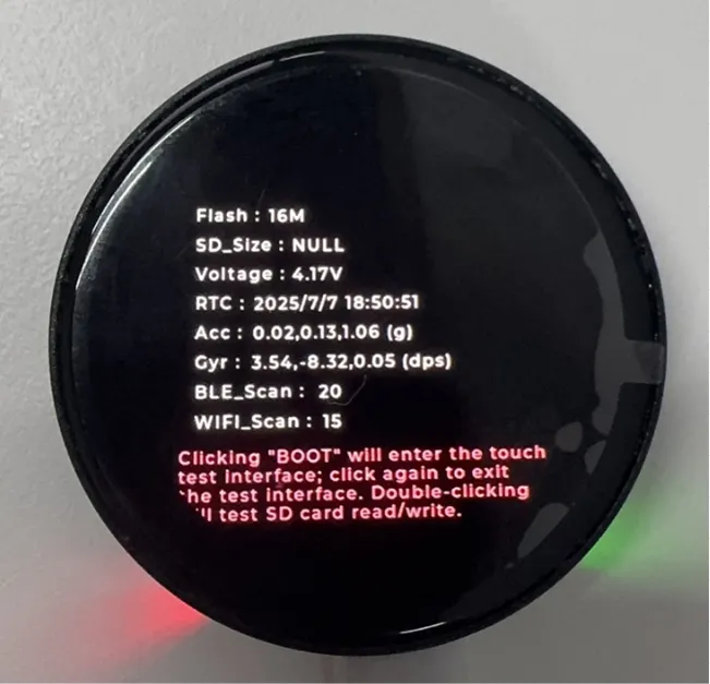 tip
tip- Displays the ESP32C6 stacked Flash
- Displays the actual capacity of the inserted TF card
- Displays the voltage of the connected lithium battery
- Real-time display of RTC time and QMI attitude data
- Scans for nearby Bluetooth and Wi-Fi devices
-
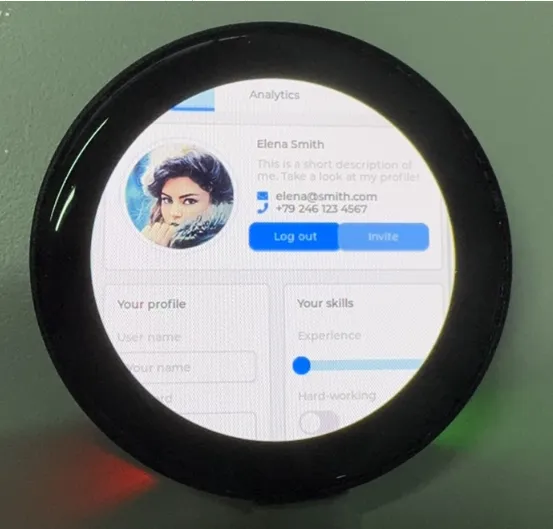
Click the BOOT button on the onboard hardware information interface to enter the Touch function interface, as shown:
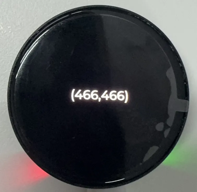
-
Click the BOOT button again to exit the Touch function interface and activate the microphone recording and speaker playback functions:
tip- Speak into the microphone, and the speaker will automatically play back the recorded sound.
- Press and hold the BOOT button to play music; release to stop.
-
Test the TF card read/write function, as shown:
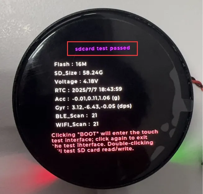 tip
tip- Double-click the BOOT button to perform the test.
-
Swipe left to enter the AMOLED backlight setting interface, as shown:
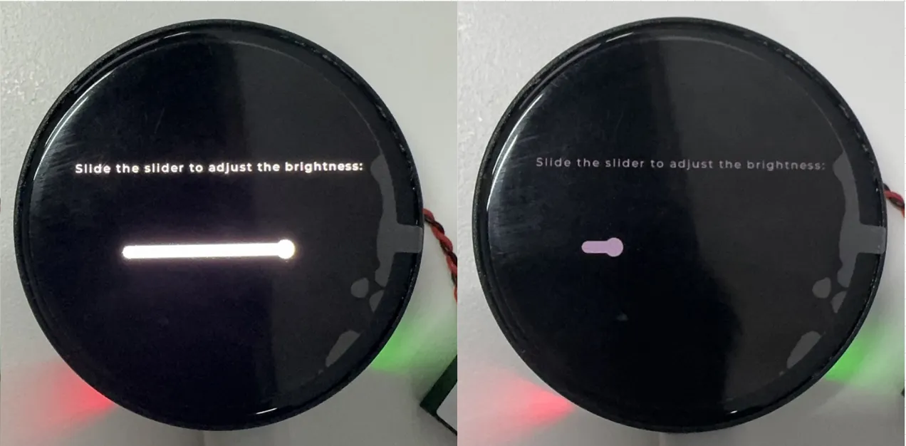
-
Power the board using only a lithium battery, with the PWR button controlling the power:
tip- Press and hold the PWR button to turn on the system power, and press and hold it again to turn off the system power