Section 3 Create Project
The core logic of this tutorial applies to all ESP32 boards, but all the operation steps are explained using the example of the Waveshare ESP32-S3-Zero mini development board. If you are using a development board of another model, please modify the corresponding settings according to the actual situation.
This section explains how to create an ESP-IDF project using VS Code and demonstrates the practical example of illuminating an externally connected LED.
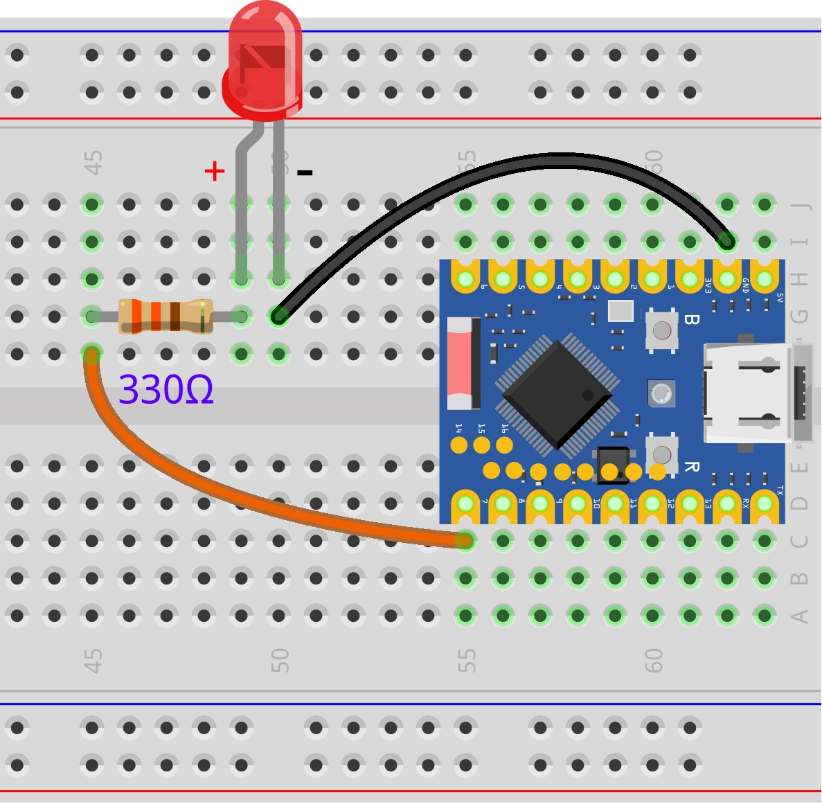
1. Circuit Assembly
Components required:
- LED * 1
- 330Ω resistor * 1
- Breadboard * 1
- Wires
- ESP32 development board (Waveshare ESP32-S3-Zero Mini Development Board)
Connect the circuit according to the wiring diagram below:
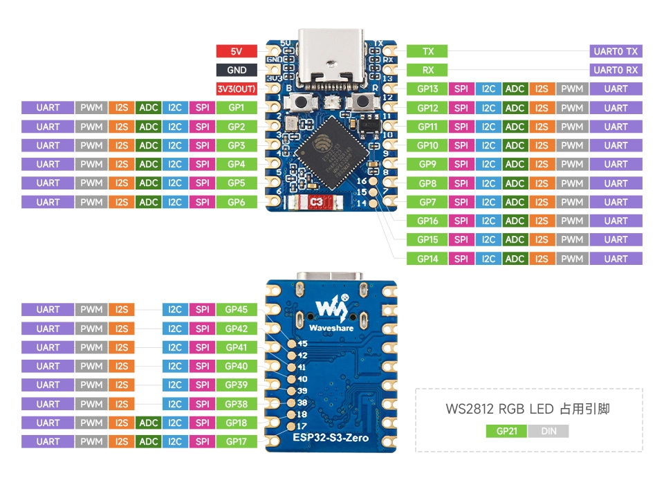
ESP32-S3-Zero Pinout Diagram
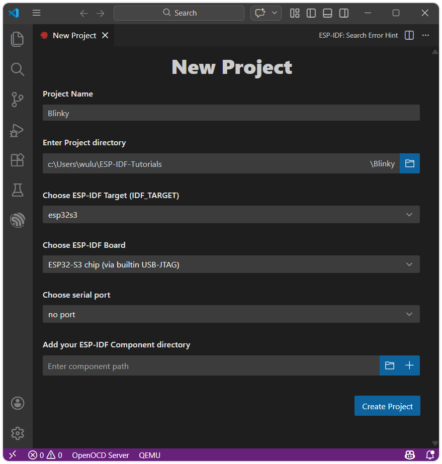
2. Create a Project from a Template
-
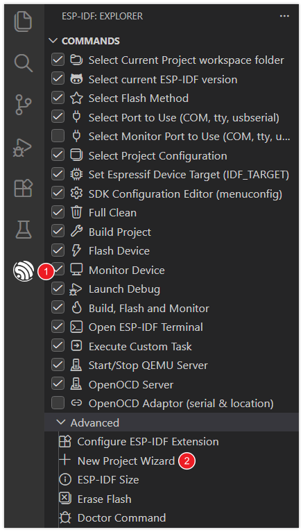
Open VS Code, click the ESP-IDF extension, and open the New Project Wizard under Advanced.
-
Select the ESP-IDF version.

-
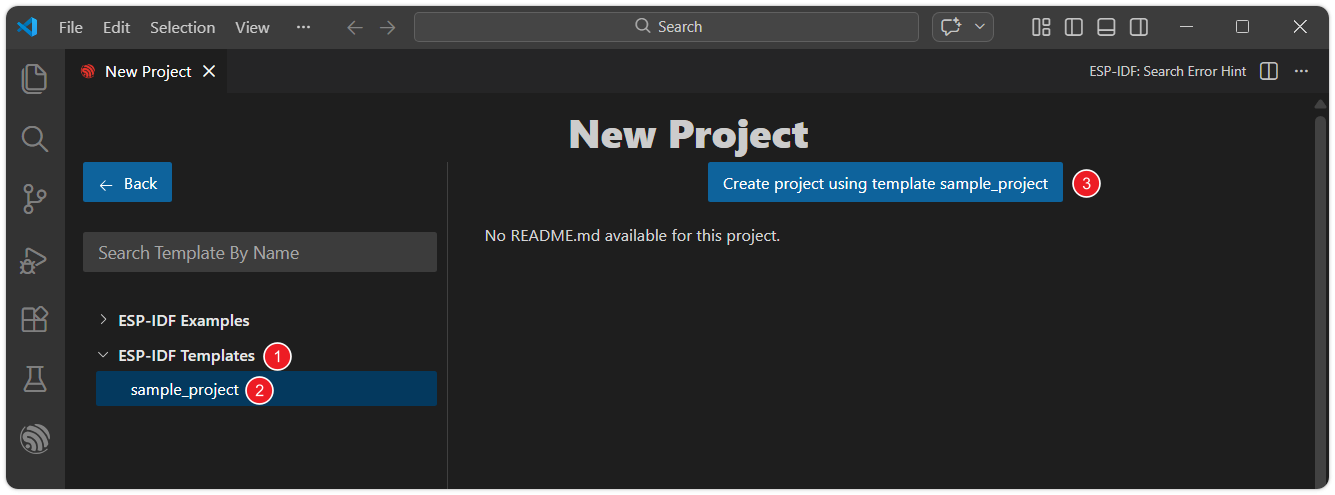
Under ESP-IDF Templates, select the sample_project template, then click Create project using template sample_project.
-
Set the project name, storage location, and other parameters. Board-related parameters can be modified after the project is created. Once done, click Create Project.
warningThe project path must not contain spaces, Chinese characters, or special characters.
-
Click Open Project to open the new project.

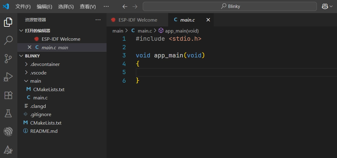
3. Write Code
ESP-IDF will generate many files and folders for the project. In this getting started guide, it is recommended to keep all the default files intact and we will only need to modify the main.c file.
-
Write the following code:
#include <stdio.h>#include "driver/gpio.h"#include "freertos/FreeRTOS.h"#include "freertos/task.h"static const gpio_num_t led_pin = GPIO_NUM_7;void app_main(void){gpio_reset_pin(led_pin); // Reset the pingpio_set_direction(led_pin, GPIO_MODE_OUTPUT); // Set the pin as output modewhile (1){gpio_set_level(led_pin, 1); // Set the pin to high level, turn on the LEDprintf("LED state: ON\n"); // Print the current state of the LEDvTaskDelay(pdMS_TO_TICKS(1000)); // Task delay of 1000 milliseconds (1 second)gpio_set_level(led_pin, 0); // Set the pin to low level, turn off the LEDprintf("LED state: OFF\n"); // Print the current state of the LEDvTaskDelay(pdMS_TO_TICKS(1000)); // Delay the task again for 1000 milliseconds (1 second)}} -
Code Navigation and Syntax Highlighting
For code navigation and C/C++ syntax highlighting, it is recommended to use the Microsoft C/C++ Extension.
After installing the plugin, VS Code is usually able to automatically perform syntax highlighting and recognize macro definitions, library variables, etc. If you encounter red squiggly lines indicating undefined symbols or other issues while writing code, these can generally be resolved by building the project once. Alternatively, you can follow these steps to fix the issue:
-
Typically, the C/C++ language extension relies on a file named
compile_commands.json, which is located in the project's build directory. You can use theESP-IDF: Run idf.py reconfigure Taskto generate this file. -
Use the shortcut keys Ctrl + Shift + P to open the VS Code command panel. Then run
ESP-IDF: Run idf.py reconfigure Task.
-
4. Build and Flash the Code
-
Configure Flash Options
Firstly, before building and flashing, please make sure to check and set the correct target device, serial port, and flashing method. Refer to Section 2 Run Demo 1.3 。

-
Click
 to automatically perform the build, flash, and monitor steps in sequence with one click.
 -
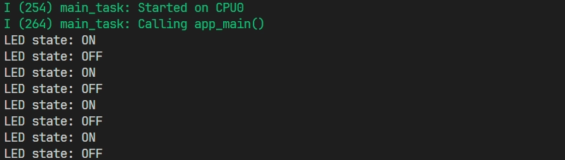
After the flashing is complete, you will see the LED start blinking. At the same time, the serial monitor will start and output the following log information:
5. Code Analysis
-
First include the required libraries:
#include "driver/gpio.h"#include "freertos/FreeRTOS.h"#include "freertos/task.h"stdio.h: The C standard input/output library, used here to call theprintffunction for printing information to the serial port.driver/gpio.h: The GPIO driver library provided by ESP-IDF, which includes functions for configuring and operating GPIO pins, such as setting pin direction and reading/writing pin levels.freertos/FreeRTOS.handfreertos/task.h: ESP-IDF uses FreeRTOS as its real-time operating system. These two header files provide APIs related to the operating system core and task management. Here, we mainly use thevTaskDelayfunction to achieve precise delays.
-
GPIO pin definition
static const gpio_num_t led_pin = GPIO_NUM_7;- This line of code defines a constant
led_pinto represent the GPIO pin number to which the LED is connected. gpio_num_tis an enumeration type used in ESP-IDF to represent GPIO numbers.GPIO_NUM_7is one of the values in this enumeration, representing the general-purpose I/O pin numbered 7 (GPIO7). For readability and type safety, it is recommended to useGPIO_NUM_7instead of the literal value7.
noteThe availability and limitations of GPIO7 vary across different chips. Please check the pin definitions of the development board you are using.
- This line of code defines a constant
-
GPIO initialization
gpio_reset_pin(led_pin); // Reset the pingpio_set_direction(led_pin, GPIO_MODE_OUTPUT); // Set the pin as output modeInside the
app_mainfunction, the GPIO pins are first initialized and configured.gpio_reset_pin(led_pin);: Resets the pin to its default state before configuration, which helps avoid unexpected issues.gpio_set_direction(led_pin, GPIO_MODE_OUTPUT);: This line of code sets the selectedled_pin(GPIO 7) to the output mode.
-
Infinite loop
while(1)In FreeRTOS task functions,
while(1)is typically used to keep the task running continuously. This ensures the task remains managed by the FreeRTOS scheduler and will not exit unless explicitly deleted viavTaskDelete(). By combining an infinite loop with functions likevTaskDelay(), the task can perform operations periodically while yielding the CPU to other tasks, enabling concurrent multitasking.while (1){gpio_set_level(led_pin, 1); // Set the pin to high level, turn on the LEDprintf("LED state: ON\n"); // Print the current state of the LEDvTaskDelay(pdMS_TO_TICKS(1000)); // Task delay of 1000 milliseconds (1 second)gpio_set_level(led_pin, 0); // Set the pin to low level, turn off the LEDprintf("LED state: OFF\n"); // Print the current state of the LEDvTaskDelay(pdMS_TO_TICKS(1000)); // Delay the task again for 1000 milliseconds (1 second)}-
gpio_set_level(led_pin, 1);: Sets theled_pinto output a high logic level. -
printf(): ESP-IDF supports the standard Cprintf()function, allowing information to be output to the serial terminal for debugging and status monitoring. -
vTaskDelay(pdMS_TO_TICKS(1000));:This function delays the current FreeRTOS task for a specified number of ticks. During the delay, the task enters the blocked state, releasing the CPU for use by other tasks. The macro
pdMS_TO_TICKS(1000)converts 1000 milliseconds into the corresponding tick count, ensuring a precise 1000-millisecond delay. This process is non-blocking for the system. For more details, please refer to this link.
-