Section 2 Run Example
The core logic of this tutorial applies to all ESP32 boards, but all the operation steps are explained using the example of the Waveshare ESP32-S3-Zero mini development board. If you are using a development board of another model, please modify the corresponding settings according to the actual situation.
Before following this guide, you need to install the ESP-IDF extension on VS Code and configure your development environment. If you haven't completed it yet, please follow the installation guide below:
This section will help you familiarize yourself with the ESP-IDF project structure and demonstrate the complete development process of configuring, building, flashing, and monitoring in Visual Studio Code (VS Code) based on the official "Hello World" and "Blink" examples from ESP-IDF.
1. Hello World Example
Let's start with "Hello World" example. This program prints "Hello, world!" to the device's serial monitor.
1.1 Open the Example
-
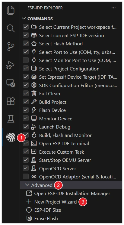
Open VS Code and click the icon to launch the ESP-IDF extension. Under the Advanced section, click New Project Wizard.
-
Select the ESP-IDF version.

-
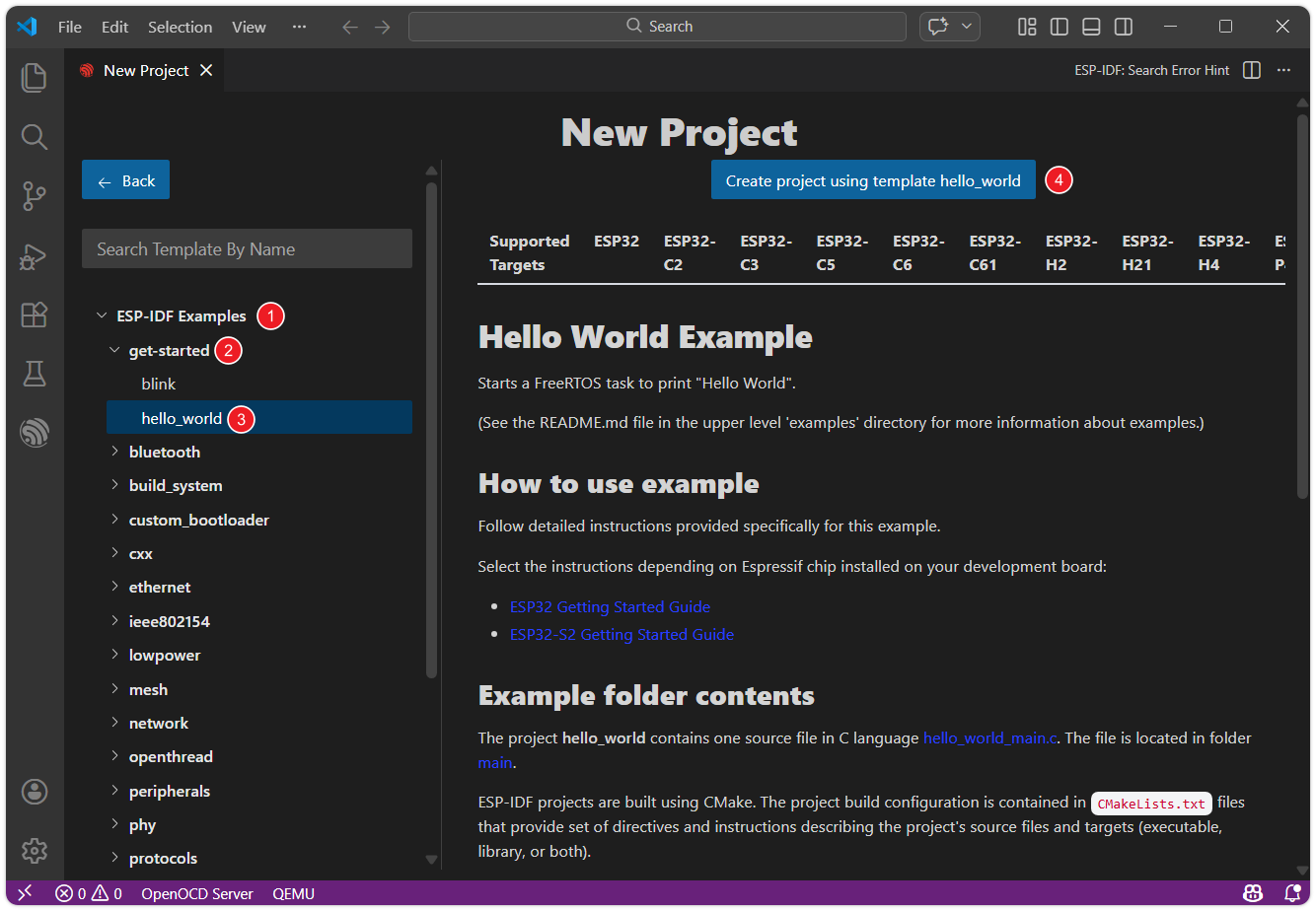
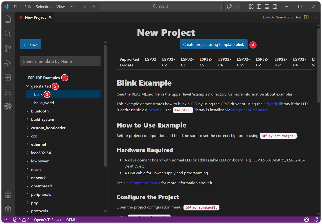
In the list, find ESP-IDF Examples, then select hello_world under the get-started category. Click Create project using template hello_world.
-
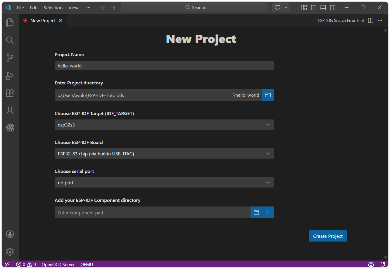
Set the project name, storage location, and other parameters. Board-related parameters can be modified after the project is created. Once done, click Create project.
warningThe project path must not contain spaces, Chinese characters, or special characters.
-
The ESP-IDF extension will automatically copy the example code to the specified location and display "Project has been created!". Click Open project to open the example project.

1.2 Project Structure
After the project is created, you can see the following core files and folder structure:
hello_world/
├── CMakeLists.txt
├── pytest_hello_world.py
├── main
│   ├── CMakeLists.txt
│   └── hello_world_main.c
└── README.md
main/: The main code directory of the project, which is also the default main component of ESP-IDF.hello_world_main.c: The C language source file of the project, containing the main logic and the entry functionapp_main.CMakeLists.txt: The component-level build script. Defines the source files, inclusion paths, etc. of the component for building system compilation links.
CMakeLists.txt(project root directory): Project-level build script. Declares this as an ESP-IDF project and includes subdirectories, etc. The project name (e.g.,project(hello_world)) is defined here.
The project will automatically generate the following after building:
build/: A directory automatically generated by the build system. It contains all the intermediate files, object files, and the final firmware binary files (.bin) generated during the compilation process.sdkconfig: The project configuration file. The relevant settings are saved into this file after modifying the configuration viamenuconfig(such as Wi-Fi, log level, etc.). It is automatically generated during the first build or configuration. Avoid manually modifyingsdkconfigto prevent breaking dependencies between configurations.
1.3 Configuration
Before building and flashing, we need to set up the target hardware and connection. The VS Code ESP-IDF extension provides an integrated toolbar in the bottom status bar, which can be set directly in the toolbar.
![]()
-
Click
 to select the flashing method: Select the UART interface.
-
Click
 to select the serial port: Connect the ESP32 development board to the computer. Click the port number and select the serial port corresponding to the development board from the list.
-
Tip: If you're unsure which port, unplug and replug the board to see which one appears.
-
Troubleshooting: If you can't find a new port, try manually entering download mode: Press and hold the "BOOT" button, plug in the USB cable, and then release the button. Then check again to find the correct port.

-
-
Click
 to select the target device: Click the chip name (e.g., esp32s3) and select the chip model that exactly matches the development board.
When setting up the target device, ESP-IDF requires configuring the corresponding toolchain and libraries. This process may take some time, please wait patiently for it to complete. For more details, please refer to the Official Documentation.
1.4 Build
Build: Use CMake/Ninja to compile and link the project and its components into executable firmware.
Click ![]() button to compile the firmware.
button to compile the firmware.
In this step, the following is generated:
- Application ELF file (for debugging)
- Flashable binary file (.bin)
- Bootloader (bootloader.bin)
- Partition table (partition-table.bin)
For detailed instructions, please refer to: ESP-IDF Build System
1.5 Flash
Flashing: The built firmware is written into the flash memory (Flash) of the target ESP32 development board via serial port or other methods.
Click ![]() button to compile the firmware.
button to compile the firmware.
During flashing, the ESP-IDF extension will automatically call the esptool.py tool to perform the actual communication and writing operations. The terminal will display the flashing progress.
1.6 Monitor
Monitor: Open the IDF Monitor to view device runtime logs and printed output, which is an important method for debugging programs and observing operational status.
Click ![]() to monitor the ESP32 serial port.
to monitor the ESP32 serial port.
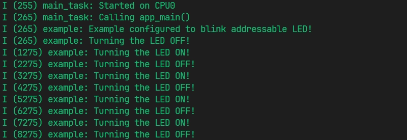
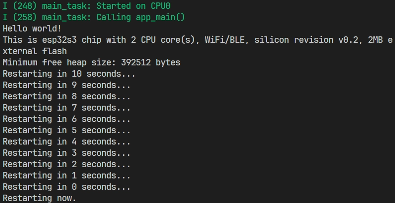
After startup, the terminal will connect to the development board. You will see the output of the "Hello World" example.
You can exit the ESP-IDF monitor using the shortcut key Ctrl + ].
1.7 Build, Flash & Monitor Combined Operations
You can also click ![]() to automatically perform the build, flash, and monitor steps in sequence with one click.
to automatically perform the build, flash, and monitor steps in sequence with one click.
2. Blink Example
Next, we will learn how to modify project configurations by using the classic "Blink" (LED Blinking) example.
This program's function is to make the onboard LED on the development board blink at a fixed frequency. The example supports both standard LEDs (GPIO) and addressable LEDs (such as WS2812, driven using RMT or SPI).
2.1 Open the Project
The steps to open the "Blink" example are exactly the same as "Hello World", just select get-started/blink from the example list.
2.2 Project Structure & sdkconfig
The Blink project has an overall structure similar to Hello World, but provides an additional set of sdkconfig default value files for different target chips.
blink/
├── CMakeLists.txt
├── main
│   ├── blink_example_main.c
│   ├── CMakeLists.txt
│   ├── idf_component.yml
│   └── Kconfig.projbuild
├── pytest_blink.py
├── README.md
├── sdkconfig.defaults
├── sdkconfig.defaults.esp32
├── sdkconfig.defaults.esp32c3
├── sdkconfig.defaults.esp32c5
├── sdkconfig.defaults.esp32c6
├── sdkconfig.defaults.esp32c61
├── sdkconfig.defaults.esp32h2
├── sdkconfig.defaults.esp32p4
├── sdkconfig.defaults.esp32s2
└── sdkconfig.defaults.esp32s3
When building, ESP-IDF applies the generic sdkconfig.defaults first, and then appends sdkconfig.defaults.<TARGET>(e.g. sdkconfig.defaults.esp32s3) based on the target chip. If the same key appears in multiple files, the value applied later overwrites the previous value.
To facilitate configuration of project-specific parameters such as LED pins, the Blink example provides a Kconfig.projbuild file under main/ to define the project configuration options (such as Blink LED type and BLINK_GPIO). These options will appear in menuconfig and will be written to sdkconfig.
2.3 Basic Project Configuration
Firstly, before building and flashing, please make sure to check and set the correct target device, serial port, and flashing method. Refer to 1.3.
![]()
2.4 Configure LED Pins
- VS Code
- menuconfig
-
Click
 to open the SDK configuration editor.
Unlike the command-line configuration tool (TUI) provided by
idf.py menuconfig, the ESP-IDF VS Code plugin offers a more intuitive graphical configuration interface. -
Modify the configuration according to the onboard LED of the development board:
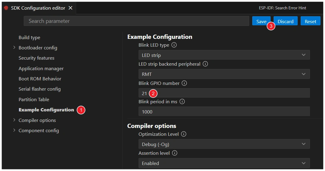
- Blink LED type: Select the LED type.
GPIO: Regular LED.LED strip: Addressable LED (such as WS2812).
- Blink GPIO number: Set the GPIO pin number connected to the LED.
- Blink period in ms: Set the period of LED blinking (unit: milliseconds).
infoThis tutorial uses the Waveshare ESP32-S3-Zero Mini Development Board, which has a WS2812 addressable LED connected to GPIO 21 pin.
- Blink LED type: Select the LED type.
-
After making the modifications, click the "Save" button.
-
Click
 to open the ESP-IDF terminal, and enter the following command:idf.py menuconfig
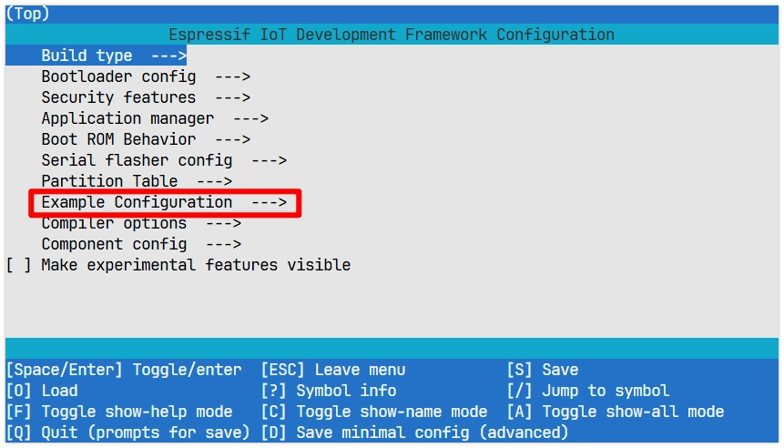
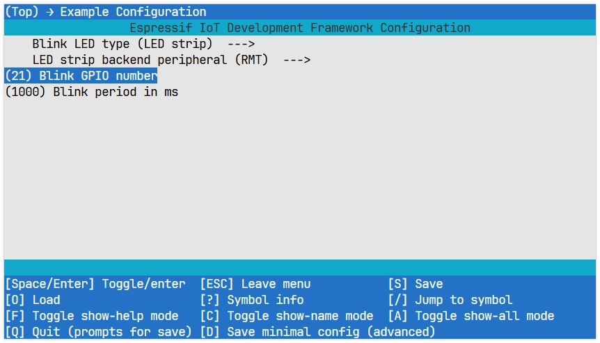
This will open a text-based menu interface that can be navigated using the arrow keys, and you can enter by pressing the Enter key or the Space key. Press Esc to return, which is used to set the specific parameters of the project.
-
Enter Example Configuration to modify the project settings:
- Blink LED type: Select the LED type.
GPIO: Regular LED.LED strip: Addressable LED (such as WS2812).
- Blink GPIO number: Set the GPIO pin number connected to the LED.
- Blink period in ms: Set the period of LED blinking (unit: milliseconds).
 info
infoThis tutorial uses the Waveshare ESP32-S3-Zero Mini Development Board, which has a WS2812 addressable LED connected to GPIO 21 pin.
- Blink LED type: Select the LED type.
-
After making changes, press S to save and Q to exit.
2.5 Build, Flash & Monitor
-
Click
 to automatically perform the build, flash, and monitor steps in sequence with one click.
 -
After the flashing is completed, you will see the LED on the development board start to blink. At the same time, the serial monitor will start and output the following log information: