Working with Arduino
This chapter includes the following sections, please read as needed:
Arduino Getting Started Tutorial
New to Arduino ESP32 development and looking for a quick start? We have prepared a comprehensive Getting Started Tutorial for you.
- Section 0: Getting to Know ESP32
- Section 1: Installing and Configuring Arduino IDE
- Section 2: Arduino Basics
- Section 3: Digital Output/Input
- Section 4: Analog Input
- Section 5: Pulse Width Modulation (PWM)
- Section 6: Serial Communication (UART)
- Section 7: I2C Communication
- Section 8: SPI Communication
- Section 9: Wi-Fi Basics
- Section 10: Web Server
- Section 11: Bluetooth
- Section 12: LVGL GUI Development
- Section 13: Comprehensive Project
Note: This tutorial uses the ESP32-S3-Zero as a reference example, and all hardware code is based on its pinout. Before you start, we recommend checking the pinout of your development board to ensure the pin configuration is correct.
Setting Up Development Environment
1. Installing and Configuring Arduino IDE
Please refer to the tutorial Installing and Configuring Arduino IDE Tutorial to download and install the Arduino IDE and add ESP32 support.
2. Installing Libraries
- When installing Arduino libraries, there are typically two methods: Online Installation and Offline Installation. If the library installation requires offline installation, you must use the provided library file.
- For most libraries, users can easily search and install them through the online Library Manager in the Arduino software. However, some open-source libraries or custom libraries are not synchronized to the Arduino Library Manager, so they cannot be acquired through online searches. In this case, users can only manually install these libraries offline.
You can click this link to download the example package for the ESP32-S3-Touch-AMOLED-1.75C board from the
Arduinodirectory. TheArduino\librariesdirectory within the package already includes all the library files required for this tutorial.
| Library/File Name | Description | Version | Installation Method |
|---|---|---|---|
| GFX Library for Arduino | ST7789 display driver graphics library | v1.6.4 | Install via library manager or manually |
| SensorLib | PCF85063, QMI8658 sensor driver library | v0.3.3 | Install via library manager or manually |
| XPowersLib | AXP2101 driver library | v0.2.6 | Install via library manager or manually |
| lvgl | LVGL display framework | v8.4.0 | Install via library manager or manually |
| Mylibrary | Board pin macro definition | —— | Install manually |
| lv_conf.h | LVGL configuration file | —— | Install manually |
There are strong dependencies between versions of LVGL and its driver libraries. For example, a driver written for LVGL v8 may not be compatible with LVGL v9. To ensure stable reproduction of the examples, it is recommended to use the specific versions listed in the table above. Mixing different library versions may cause compilation failures or runtime exceptions.
Installation Steps:
-
Download the example package.
-
Copy all folders (Arduino_DriveBus, GFX_Library_for_Arduino, etc.) in the
Arduino\librariesdirectory to the Arduino library folder.infoThe path to the Arduino libraries folder is typically:
c:\Users\<Username>\Documents\Arduino\libraries.You can also locate it within the Arduino IDE via File > Preferences, by checking the "Sketchbook location". The library folder is the
librariesfolder under this path. -
For other installation methods, please refer to: Arduino Library Management Tutorial.
Example
The Arduino examples are located in the Arduino/examples directory of the example package.
| Demo | Basic Program Description | Dependency Library |
|---|---|---|
| 01_HelloWorld | Demonstrates the basic graphics library function and can also be used to test the basic performance of display screens and the display effect of random text | GFX_Library_for_Arduino |
| 02_GFX_AsciiTable | Prints ASCII characters in rows and columns on the screen according to the screen size | GFX_Library_for_Arduino |
| 03_LVGL_AXP2101_ADC_Data | Drives the AXP2101 using the ported XPowersLib to get power-related data | GFX_Library_for_Arduino |
| 04_LVGL_QMI8658_ui | LVGL draws an acceleration line chart | LVGL, SensorLib |
| 05_LVGL_Widgets | LVGL demonstration | LVGL, Arduino_DriveBus, Adafruit_XCA9554 |
| 06_ES7210 | ES7210 driver demo, picking up human voice for detection | —— |
| 07_ES8311 | ES8311 driver example, plays simple audio | —— |
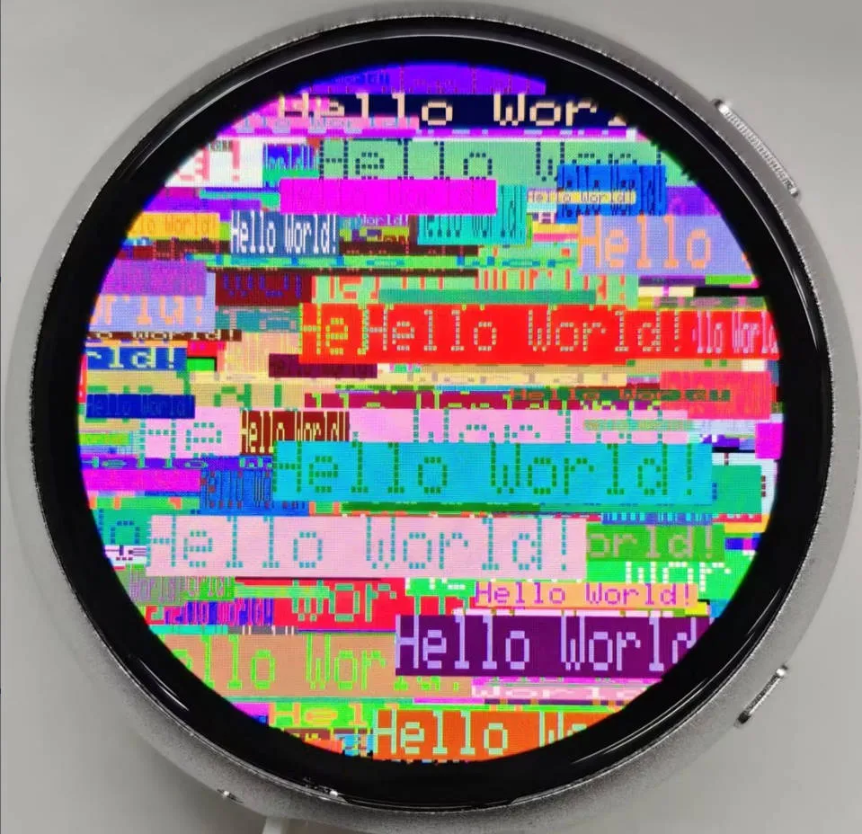
01_HelloWorld
Example Description
- This demo demonstrates how to control the SH8601 display using the Arduino GFX library, demonstrating basic graphics library functions through dynamically changing text. This code can also be used to test the basic performance of the display and the random text display effects
Hardware Connection
- Connect the development board to the computer
Code Analysis
-
Display initialization:
if (!gfx->begin()) {USBSerial.println("gfx->begin() failed!");} -
Clear the screen and display text:
gfx->fillScreen(BLACK);gfx->setCursor(10, 10);gfx->setTextColor(RED);gfx->println("Hello World!"); -
Animated display:
gfx->setCursor(random(gfx->width()), random(gfx->height()));gfx->setTextColor(random(0xffff), random(0xffff));gfx->setTextSize(random(6), random(6), random(2));gfx->println("Hello World!");
Expected Result
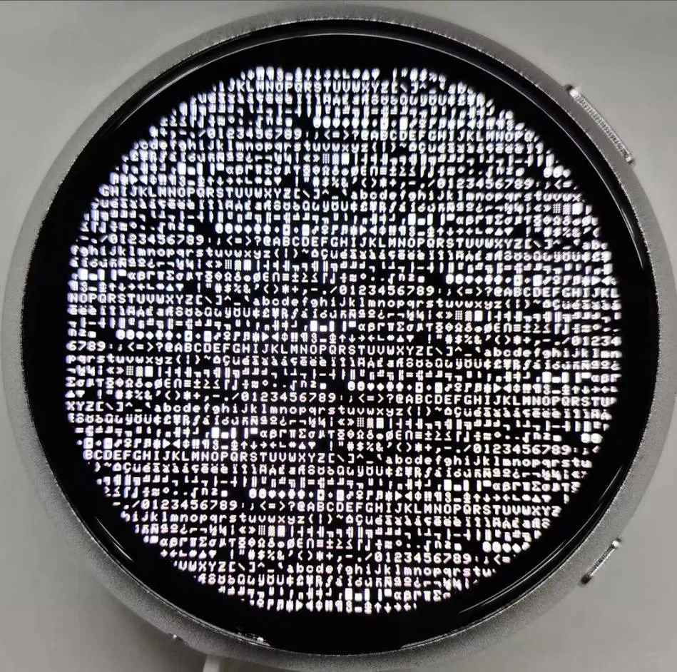
02_GFX_AsciiTable
Example Description
- This demo shows how to display a basic ASCII character table on the SH8601 display by using the Arduino GFX library on an ESP32. The core function of the code is to initialize the display and print ASCII characters in rows and columns according to the screen size
Hardware Connection
- Connect the development board to the computer
Code Analysis
-
Create data bus and graphic display objects
- Here a data bus object
busis created for communicating with the display, initialized with specific pin configurations. Then a graphics display objectgfxis created, passing parameters such as the data bus, reset pin, rotation angle, whether it is an IPS panel, and the width and height of the display
Arduino_DataBus *bus = new Arduino_ESP32QSPI(LCD_CS /* CS */, LCD_SCLK /* SCK */, LCD_SDIO0 /* SDIO0 */, LCD_SDIO1 /* SDIO1 */,LCD_SDIO2 /* SDIO2 */, LCD_SDIO3 /* SDIO3 */);Arduino_GFX *gfx = new Arduino_SH8601(bus, -1 /* RST */,0 /* rotation */, false /* IPS */, LCD_WIDTH, LCD_HEIGHT); - Here a data bus object
-
Draw row and column numbers and character table
- First set the text color to green and print the row numbers one by one on the display. Then set the text color to blue and print the column numbers. Next, use a loop to draw each character individually, forming the character table, with each character using white foreground and black background
gfx->setTextColor(GREEN);for (int x = 0; x < numRows; x++) {gfx->setCursor(10 + x * 8, 2);gfx->print(x, 16);}gfx->setTextColor(BLUE);for (int y = 0; y < numCols; y++) {gfx->setCursor(2, 12 + y * 10);gfx->print(y, 16);}char c = 0;for (int y = 0; y < numRows; y++) {for (int x = 0; x < numCols; x++) {gfx->drawChar(10 + x * 8, 12 + y * 10, c++, WHITE, BLACK);}}
Expected Result
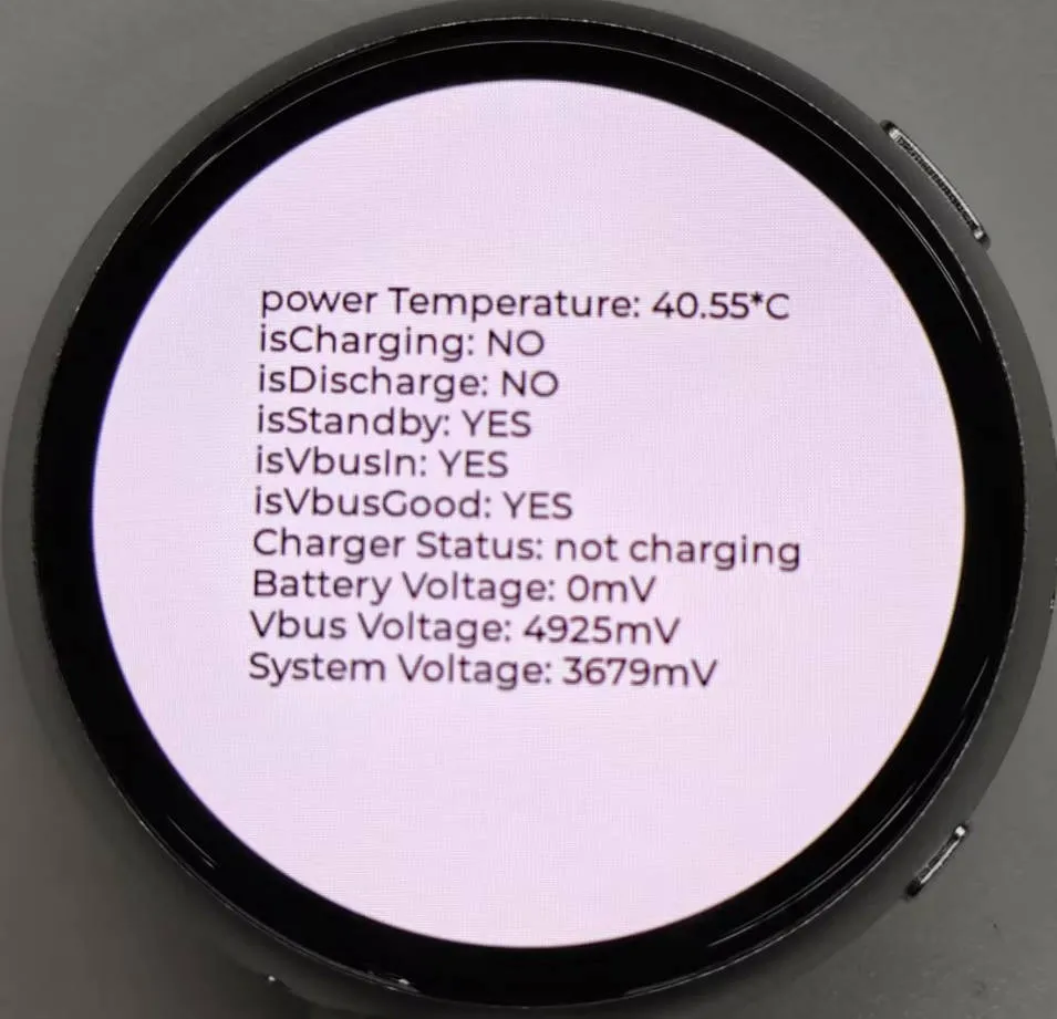
03_LVGL_AXP2101_ADC_Data
Example Description
- This demo demonstrates power management using the XPowers library under LVGL, and provides PWR custom button control for screen on and off actions
Hardware Connection
- Connect the development board to the computer
Code Analysis
-
Screen on/off function
void toggleBacklight() {USBSerial.println(backlight_on);if (backlight_on) {for (int i = 255; i >= 0; i--) {gfx->Display_Brightness(i);delay(3);}}else{for(int i = 0;i <= 255;i++){gfx->Display_Brightness(i);delay(3);}}backlight_on = !backlight_on;}
Expected Result
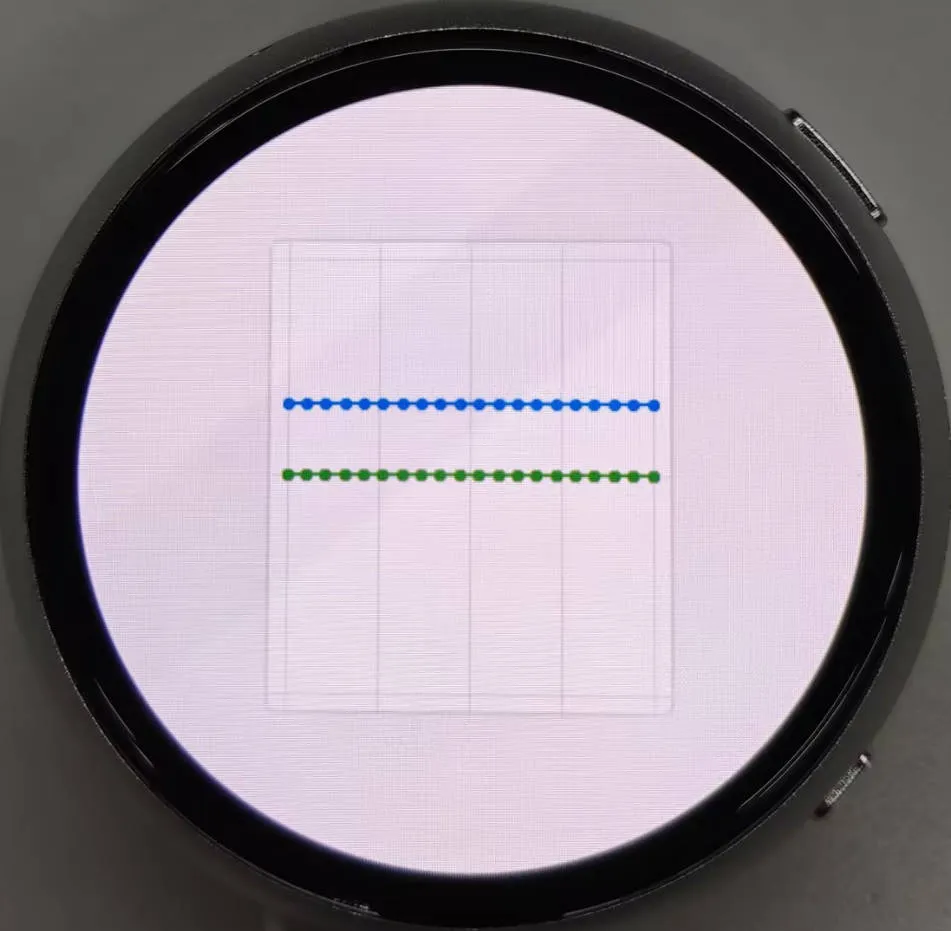
04_LVGL_QMI8658_ui
Example Description
- This demo demonstrates using LVGL for graphical display, communicating with the QMI8658 IMU to obtain accelerometer and gyroscope data
Hardware Connection
- Connect the development board to the computer
Code Analysis
-
setup: Responsible for initializing various hardware devices and the LVGL graphics library environment- Serial initialization:
USBSerial.begin(115200)prepares for serial debugging - Touch controller initialization: Continuously attempts to initialize the touch controller FT3168. If initialization fails, prints an error message and waits with a delay; prints a success message upon success
- Graphics display initialization: Initializes the graphics display device gfx, sets brightness, and prints LVGL and Arduino version information Then initializes the LVGL, including registering a print callback function for debugging, initializing the display driver and the input device driver. Creates and starts an LVGL timer. Finally creates a label and sets its initial text to "Initializing..."
- Creating a chart: Creates a chart object chart, sets chart properties such as type, range, number of data points, etc., and adds data series for the three axes of acceleration
- Acceleration sensor initialization: Initializes the acceleration sensor qmi, configures accelerometer and gyroscope parameters, enables them, and prints the chip ID and control register information
- Serial initialization:
-
looplv_timer_handler(): This is an important function in the LVGL graphics library, used to handle various timer events, animation updates, input processing, and other tasks for the graphical interface. Calling this function in each loop ensures the graphical interface runs smoothly and responds to interactions promptly- Reading acceleration sensor data: If acceleration sensor data is ready, reads acceleration data and prints it via the serial port, while updating the chart to display acceleration data. If the gyroscope data is ready, reads the gyroscope data and prints it via the serial port. Finally adds a small delay to increase data polling frequency
Expected Result
05_LVGL_Widgets
Example Description
- This example demonstrates LVGL Widgets example. The frame rate can reach 50~60 fps in dynamic states. Optimizing the SH8601 display library can achieve smoother frame rates. This can be compared with scenarios where double buffering and dual acceleration are enabled in the ESP-IDF environment
Hardware Connection
- Connect the development board to the computer
Code Analysis
setup: Responsible for initializing various hardware devices and the LVGL graphics library environment- Serial initialization:
USBSerial.begin(115200)prepares for serial debugging - I2C bus Initialization:
Wire.begin(IIC_SDA, IIC_SCL); initializes I2C bus for communicating with other I2C devices - Expansion chip initialization: Creates and initializes the expansion chip expander, sets pin modes to output, and performs some initial pin state settings
- Touch controller initialization: Continuously attempts to initialize the touch controller FT3168. If initialization fails, prints an error message and waits with a delay; prints a success message upon success
- Graphics display initialization: Initializes the graphics display device gfx, sets brightness, and obtains the width and height of the screen. Then initializes LVGL, including registering a print callback function for debugging, setting the touch controller's power mode to monitoring mode, initializing display driver and input device driver. Creates and starts an LVGL timer. Creates a label and sets its text. Finally calls
lv_demo_widgets()to showcase LVGL example widgets
- Serial initialization:
looplv_timer_handler(): This is an important function in the LVGL graphics library, used to handle various timer events, animation updates, input processing, and other tasks for the graphical interface. Calling this function in each loop ensures the graphical interface runs smoothly and responds to interactions promptlydelay(5): Adds a small delay to avoid excessive CPU resource consumption
Expected Result
06_ES7210
Example Description
- This demo demonstrates using I2S to drive the ES7210 chip, pick up sounds, and filter out human voice
Hardware Connection
- Connect the development board to the computer
Expected Result
- The device picks up audio directly without showing content on the screen.
07_ES8311
Example Description
- This demo demonstrates using I2S to drive the ES8311 chip, playing the converted binary audio file
Hardware Connection
- Connect the development board to the computer
Code Analysis
es8311_codec_init: Initializes the ES8311 audio codec- Creates an ES8311 codec handle es_handle
- Configures ES8311 clock parameters, including master clock and sampling clock frequencies, clock polarity, etc.
- Initializes the codec, sets audio resolution to 16-bit
- Configures sampling frequency
- Configures microphone-related parameters, such as turning off the microphone, setting volume and microphone gain
setup: Performs overall initialization settings, including serial port, pins, I2S, and the ES8311 codec- Initializesserial port for debugging output
- Sets a specific pin as output and pulls it high
- Configures the I2S bus, setting pins, operating mode, sample rate, data bit width, channel mode, etc.
- Initializes the I2C bus
- Calls
es8311_codec_initfunction to initialize the ES8311 codec - Plays a pre-defined audio data (canon_pcm) via the I2S bus
Expected Result
- The device will play auido directly without showing content on the screen