Working with Arduino
This chapter includes the following sections, please read as needed:
Arduino Getting Started Tutorial
New to Arduino ESP32 development and looking for a quick start? We have prepared a comprehensive Getting Started Tutorial for you.
- Section 0: Getting to Know ESP32
- Section 1: Installing and Configuring Arduino IDE
- Section 2: Arduino Basics
- Section 3: Digital Output/Input
- Section 4: Analog Input
- Section 5: Pulse Width Modulation (PWM)
- Section 6: Serial Communication (UART)
- Section 7: I2C Communication
- Section 8: SPI Communication
- Section 9: Wi-Fi Basics
- Section 10: Web Server
- Section 11: Bluetooth
- Section 12: LVGL GUI Development
- Section 13: Comprehensive Project
Note: This tutorial uses the ESP32-S3-Zero as a reference example, and all hardware code is based on its pinout. Before you start, we recommend checking the pinout of your development board to ensure the pin configuration is correct.
Setting Up Development Environment
1. Installing and Configuring Arduino IDE
Please refer to the tutorial Installing and Configuring Arduino IDE Tutorial to download and install the Arduino IDE and add ESP32 support.
2. Installing Libraries
- When installing Arduino libraries, there are typically two methods: Online Installation and Offline Installation. If the library installation requires offline installation, you must use the provided library file.
- For most libraries, users can easily search and install them through the online Library Manager in the Arduino software. However, some open-source libraries or custom libraries are not synchronized to the Arduino Library Manager, so they cannot be acquired through online searches. In this case, users can only manually install these libraries offline.
- The sample program package for the ESP32-S3-ePaper-3.97 development board can be downloaded from here. The
Arduino\librariesdirectory within the package already includes all the library files required for this tutorial.
| Library/File Name | Description | Version | Installation Method |
|---|---|---|---|
| SensorLib | Sensor library | v0.3.1 | "Install Online" or "Install Offline" |
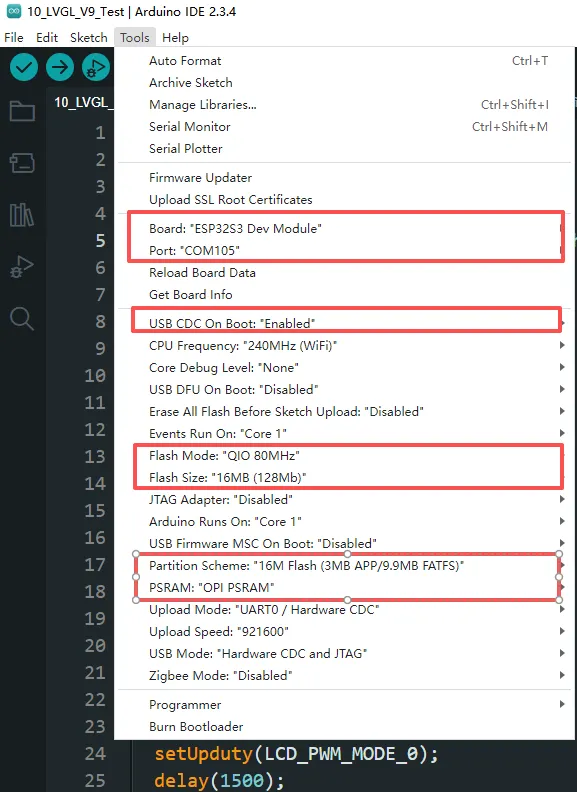
3. Arduino Project Parameter Settings
Example
The Arduino examples are located in the Arduino/examples directory of the example package.
| Demo | Basic Program Description | Dependency Library |
|---|---|---|
| 01_Audio_Test | Drives ES8311 to play audio | - |
| 02_E-Paper_Example | 3.97inch e-Paper display demo | - |
| 03_I2C_PCF85063 | RTC demo | - |
| 04_I2C_SHTC3 | Temperature and humidity sensor demo | SensorLib |
| 05_SD_Test | TF card demo | - |
| 06_QMI8658A | 6-axis gyroscope demo | SensorLib |
01_Audio_Test
Description
- This example drives the ES8311 audio codec to play music.
Hardware Connection
- Connect the board to the computer using a USB cable
Code Analysis
-
Configure and initialize the ES8311 audio codec.
void setup() {Serial.begin(115200);Wire.begin(I2C_SDA, I2C_SCL);pinMode(PA_CTRL, OUTPUT);digitalWrite(PA_CTRL, HIGH);es8311_codec_init();setupI2S();Serial.println("I2S Initialized");} -
Continuously write built-in audio data to the I2S bus for looped playback.
i2s.write((uint8_t *)audio_data, AUDIO_SAMPLES * 2);
Operation Result
- The device will play auido directly without showing content on the screen
02_E-Paper_Example
Description
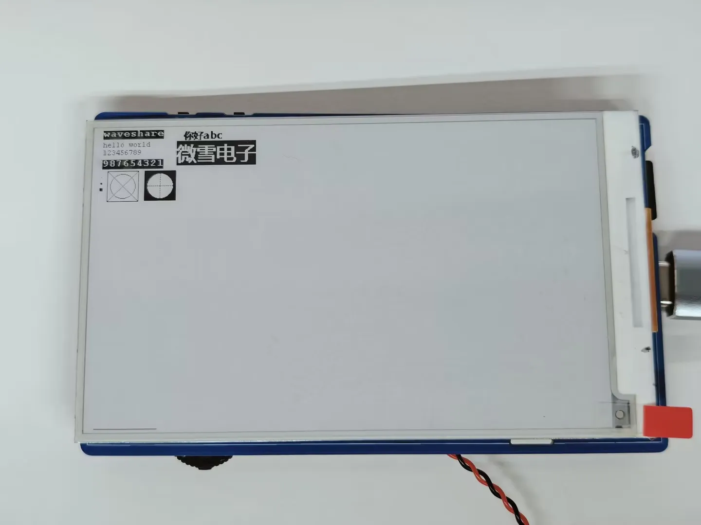
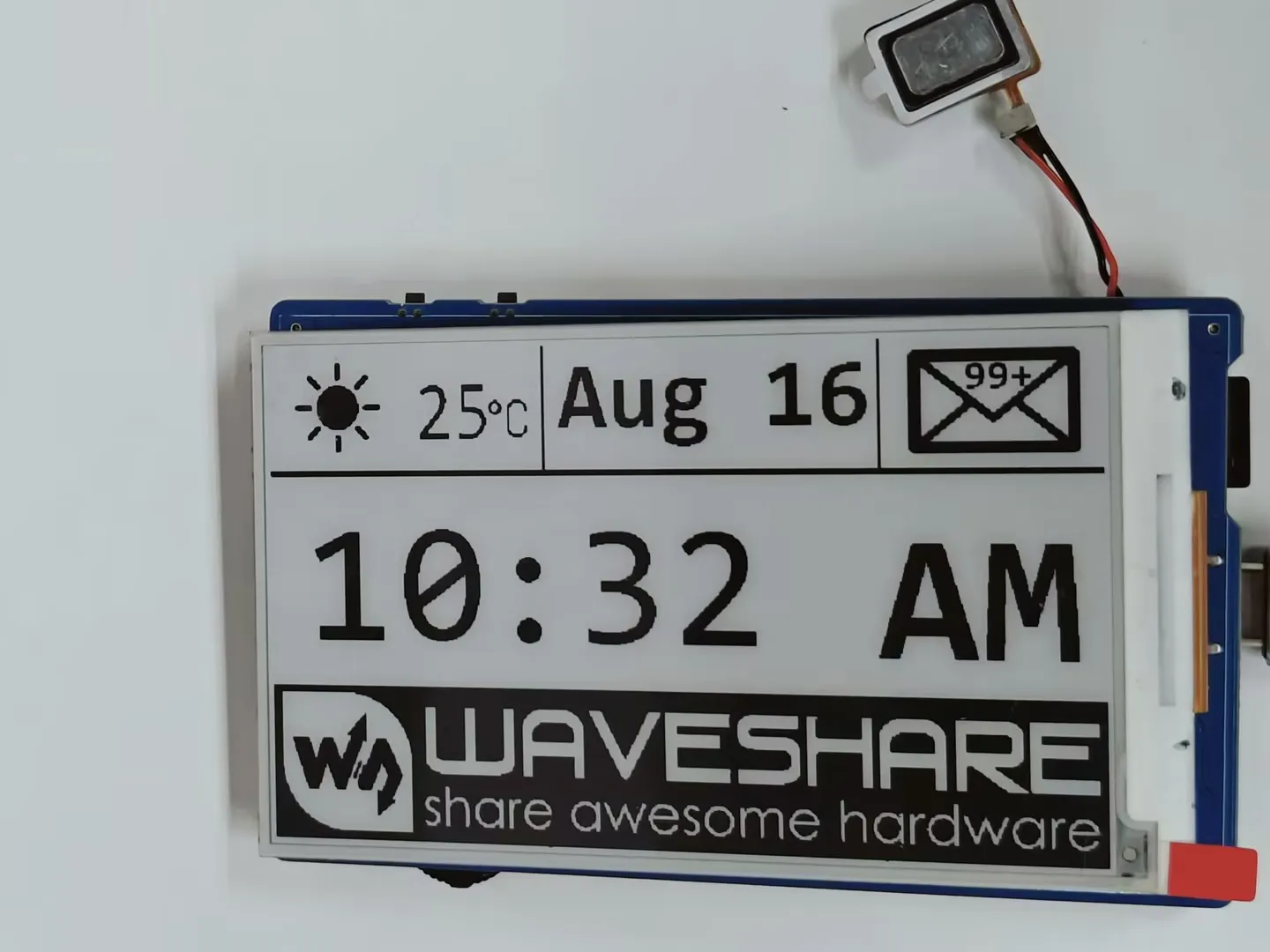
- This is a local Arduino example for the 3.97inch e-Paper display. It initializes and clears the e-Paper display, displays an image, draws basic shapes and text, and performs partial refresh to dynamically display the time.
Hardware Connection
- Connect the board to the computer using a USB cable
Code Analysis
-
Display a predefined image.
#if 1 // show bmpEPD_3IN97_Init_Fast();printf("show image for array\r\n");EPD_3IN97_Display(gImage_image);DEV_Delay_ms(1500);#endif -
Draw basic shapes, Chinese/English text, numbers, and refresh the display.
#if 1 // Drawing on the image//1.Select ImageEPD_3IN97_Init();printf("SelectImage:BlackImage\r\n");Paint_SelectImage(BlackImage);Paint_Clear(WHITE);// 2.Drawing on the imageDebug("Drawing:BlackImage\r\n");Paint_DrawPoint(10, 80, BLACK, DOT_PIXEL_1X1, DOT_STYLE_DFT);Paint_DrawPoint(10, 90, BLACK, DOT_PIXEL_2X2, DOT_STYLE_DFT);Paint_DrawPoint(10, 100, BLACK, DOT_PIXEL_3X3, DOT_STYLE_DFT);Paint_DrawLine(20, 70, 70, 120, BLACK, DOT_PIXEL_1X1, LINE_STYLE_SOLID);Paint_DrawLine(70, 70, 20, 120, BLACK, DOT_PIXEL_1X1, LINE_STYLE_SOLID);Paint_DrawRectangle(20, 70, 70, 120, BLACK, DOT_PIXEL_1X1, DRAW_FILL_EMPTY);Paint_DrawRectangle(80, 70, 130, 120, BLACK, DOT_PIXEL_1X1, DRAW_FILL_FULL);Paint_DrawCircle(45, 95, 20, BLACK, DOT_PIXEL_1X1, DRAW_FILL_EMPTY);Paint_DrawCircle(105, 95, 20, WHITE, DOT_PIXEL_1X1, DRAW_FILL_FULL);Paint_DrawLine(85, 95, 125, 95, BLACK, DOT_PIXEL_1X1, LINE_STYLE_DOTTED);Paint_DrawLine(105, 75, 105, 115, BLACK, DOT_PIXEL_1X1, LINE_STYLE_DOTTED);Paint_DrawString_EN(10, 0, "waveshare", &Font16, BLACK, WHITE);Paint_DrawString_EN(10, 20, "hello world", &Font12, WHITE, BLACK);Paint_DrawNum(10, 33, 123456789, &Font12, BLACK, WHITE);Paint_DrawNum(10, 50, 987654321, &Font16, WHITE, BLACK);Paint_DrawString_CN(130, 0, " 你好 abc", &Font12CN, BLACK, WHITE);Paint_DrawString_CN(130, 20, "微雪电子", &Font24CN, WHITE, BLACK);printf("EPD_Display\r\n");EPD_3IN97_Display_Base(BlackImage);DEV_Delay_ms(3000);#endif
Operation Result
-
The screen refreshes and displays the content.
03_I2C_PCF85063
Description
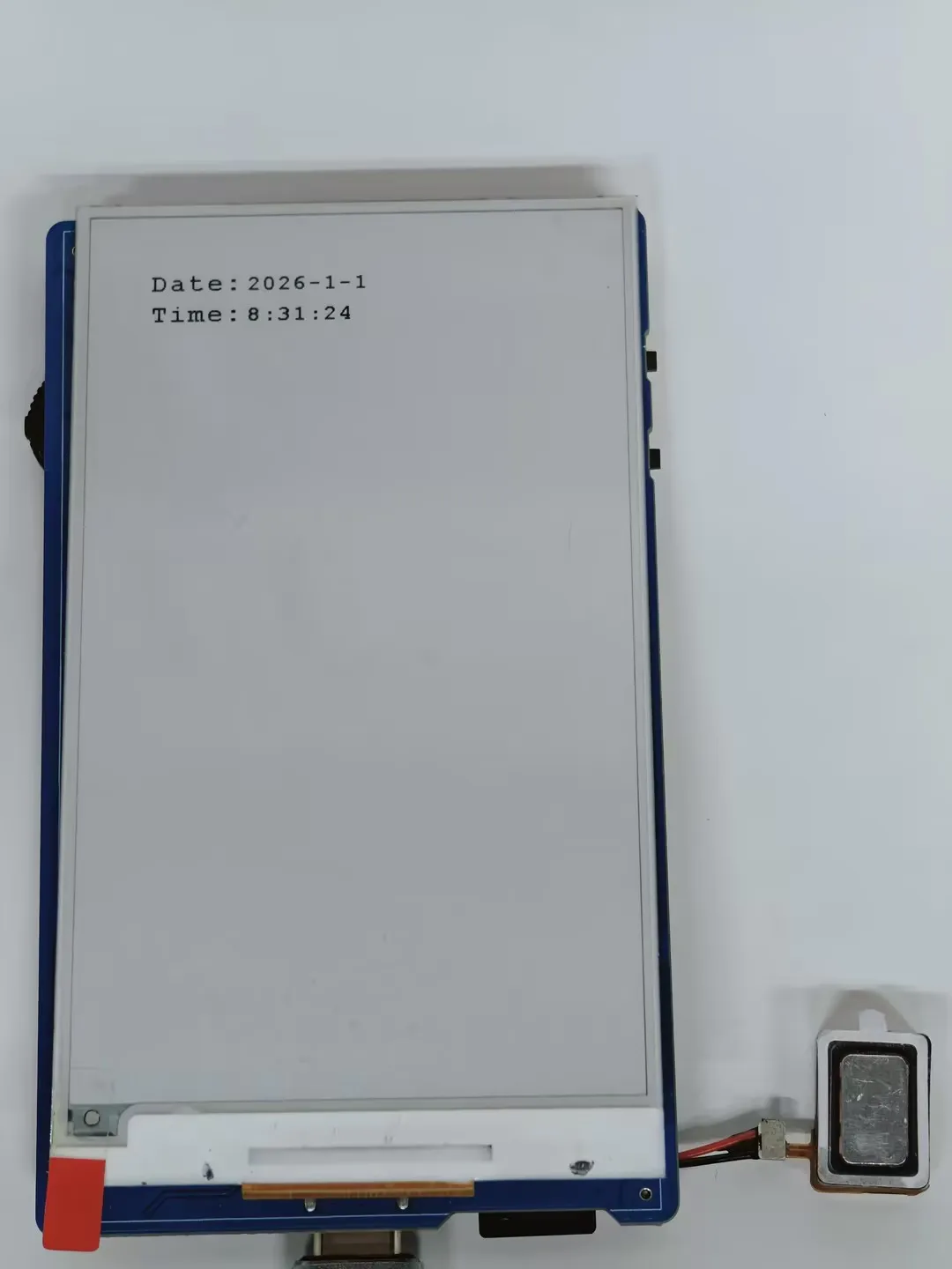
- This example uses the onboard PCF85063 RTC chip to dynamically display time on the 3.97inch e-Paper screen, combining it with the I2C interface RTC real-time clock module.
Hardware Connection
- Connect the board to the computer using a USB cable
Code Analysis
-
Continuously reads the RTC time, formats it into a string, and performs a partial refresh on the e-paper to display it.
void i2c_rtc_loop_task(void *arg){char buff[80];for(;;){RtcDateTime_t datetime = rtc_dev->get_rtcTime();printf("%d/%d/%d %d:%d:%d \n",datetime.year,datetime.month,datetime.day,datetime.hour,datetime.minute,datetime.second);Paint_NewImage(BlackImage, Font20.Height *3, Font20.Width * 8, 270, WHITE);Paint_SelectImage(BlackImage);Paint_Clear(WHITE);sprintf(buff, "%d-%d-%d", datetime.year,datetime.month,datetime.day);Paint_DrawString_EN(0, 5, buff, &Font20, WHITE, BLACK);sprintf(buff, "%d:%d:%d", datetime.hour,datetime.minute,datetime.second);Paint_DrawString_EN(0, 35, buff, &Font20, WHITE, BLACK);EPD_3IN97_Display_Partial(BlackImage, 50, 250, 50 + Font20.Height*3 , 250 + Font20.Width * 8);vTaskDelay(pdMS_TO_TICKS(500));}}
Operation Result
-
The e-Paper display partially refreshes to show the time.
04_I2C_SHTC3
Description
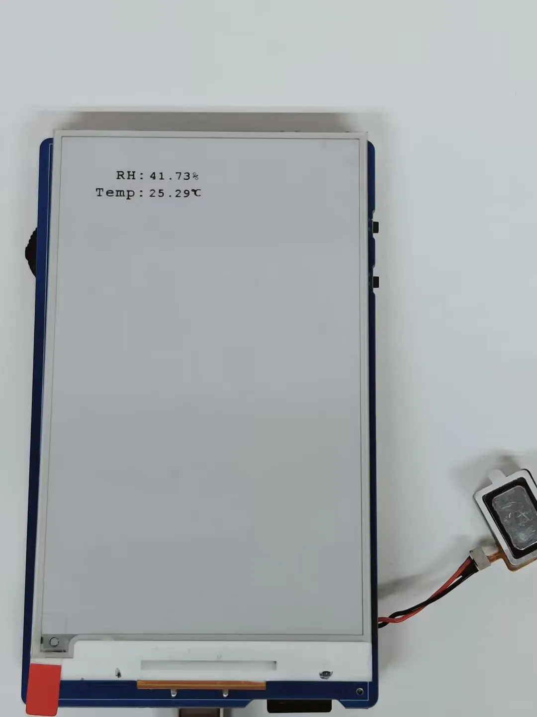
- This example uses the onboard SHTC3 temperature and humidity sensor to dynamically display temperature and humidity data on the 3.97inch e-Paper display.
Hardware Connection
- Connect the board to the computer using a USB cable
Code Analysis
-
Continuously reads sensor data and partially refreshes the e-Paper to display temperature and humidity.
void i2c_SHTC3_loop_task(void *arg){char buff[80];for(;;){shtc3_data_t shtc3_data = shtc3_dev->readTempHumi();printf("RH:%.2f%%,Temp:%.2f°C \n",shtc3_data.RH,shtc3_data.Temp);Paint_NewImage(BlackImage, Font20.Height *3, Font20.Width * 8, 270, WHITE);Paint_SelectImage(BlackImage);Paint_Clear(WHITE);sprintf(buff, "%.2f%%",shtc3_data.RH);Paint_DrawString_EN(0, 5, buff, &Font20, WHITE, BLACK);sprintf(buff, "%.2f", shtc3_data.Temp);Paint_DrawString_EN(0, 35, buff, &Font20, WHITE, BLACK);Paint_DrawString_CN(Font20.Width * 5, 30, "℃", &Font12CN, WHITE, BLACK);EPD_3IN97_Display_Partial(BlackImage, 50, 250, 50 + Font20.Height*3 , 250 + Font20.Width * 8);vTaskDelay(pdMS_TO_TICKS(1000));}}
Operation Result
-
The e-Paper display partially refreshes to show the temperature and humidity.
05_SD_Test
Description
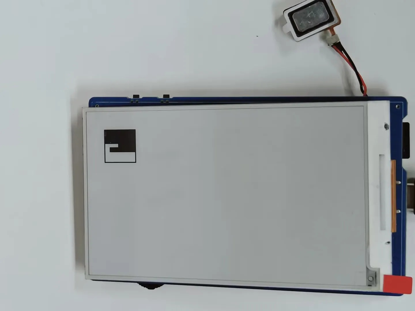
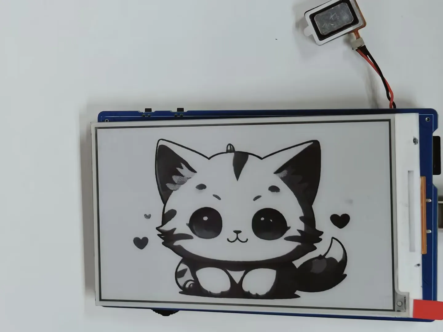
- This example reads BMP images from a TF card and refreshes them on the e-Paper display.
Hardware Connection
- Connect the board to the computer using a USB cable
- Insert the TF card module with a TF card containing a bmp folder with images in the root directory.
Code Analysis
-
Configure and mount the TF card.
//sdcard initSerial.begin(115200);delay(1000);SD_MMC.setPins(SD_CLK, SD_CMD, SD_D0, SD_D1, SD_D2, SD_D3);if (!SD_MMC.begin( "/sdcard", true)) {printf("TF card failed to mount\r\n");return;}printf("TF card success to mount\r\n"); -
Display images.
printf("show BMP-------------------------\r\n");EPD_3IN97_Init_Fast();Paint_Clear(WHITE);GUI_ReadBmp("/sdcard/bmp/100x100.bmp", 50, 50);EPD_3IN97_Display_Fast(Image);printf("100*100 BMP Load OK!\r\n");DEV_Delay_ms(1000);Paint_Clear(WHITE);GUI_ReadBmp("/sdcard/bmp/3in97.bmp", 50, 0);EPD_3IN97_Display_Fast(Image);printf("800*480 BMP Load OK!\r\n");DEV_Delay_ms(3000); -
Display 4-grayscale BMP image.
EPD_3IN97_Init_4GRAY();Paint_NewImage(Image, EPD_3IN97_WIDTH, EPD_3IN97_HEIGHT, 0, WHITE);Paint_SetScale(4);Paint_Clear(WHITE);if(GUI_ReadBmp_4Gray("/sdcard/bmp/3in97_4Gray.bmp", 0, 0) == 0){printf("4Gray BMP Load OK!\r\n");}else{printf("4Gray BMP Load Failed!\r\n");}EPD_3IN97_Display_4Gray(Image);DEV_Delay_ms(3000);
Operation Result
-
Reads and displays images from the TF card.
06_QMI8658A
Description
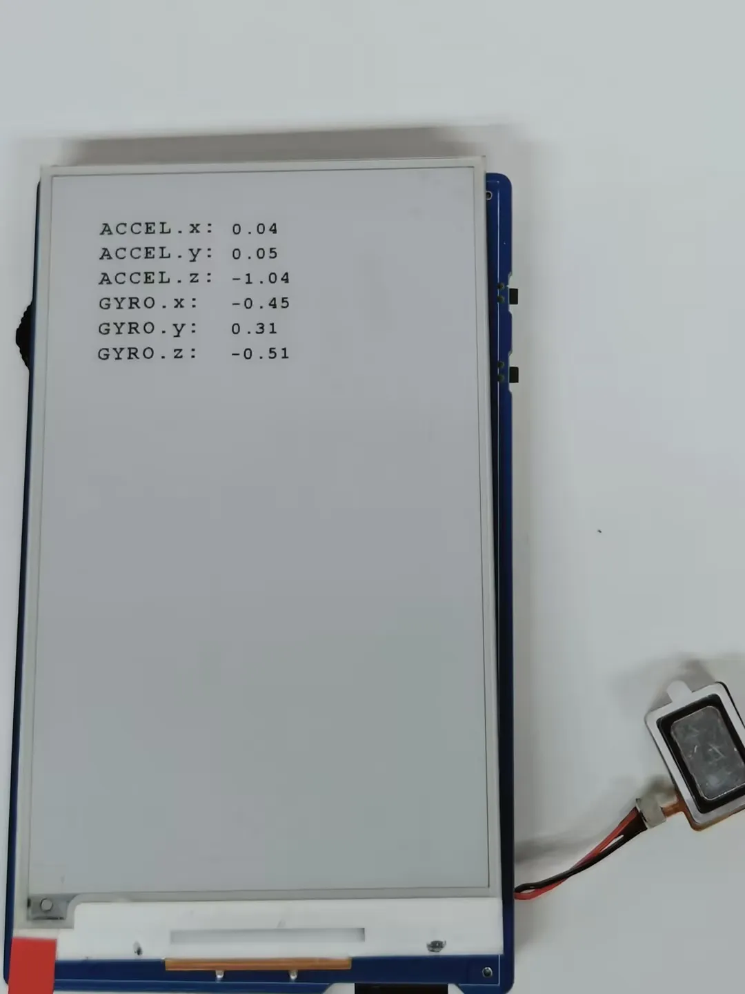
- This example uses the onboard QMI8658 6-axis IMU sensor and displays the values on the e-Paper screen.
Hardware Connection
- Connect the board to the computer using a USB cable
Code Analysis
-
Check if the data is ready, read and print the sensor data, and call the display function to update the display data on the e-Paper screen.
if (qmi.getDataReady()) {if (qmi.getAccelerometer(acc.x, acc.y, acc.z)) {Serial.print("ACCEL.x:"); Serial.print(acc.x); Serial.print(",");Serial.print("ACCEL.y:"); Serial.print(acc.y); Serial.print(",");Serial.print("ACCEL.z:"); Serial.print(acc.z); Serial.println();}if (qmi.getGyroscope(gyr.x, gyr.y, gyr.z)) {Serial.print(" GYRO.x:"); Serial.print(gyr.x); Serial.print(",");Serial.print(" GYRO.y:"); Serial.print(gyr.y); Serial.print(",");Serial.print(" GYRO.z:"); Serial.print(gyr.z); Serial.println();}qmi8658_data_show();}
Operation Result
-
The e-Paper display partially refreshes to show 6-axis gyroscope sensor data.