Traffic Light
Important Note on Board Compatibility
The core logic of this tutorial applies to all ESP32 development boards. However, all operational steps are explained using the Waveshare ESP32-S3-Zero Mini Development Board as an example. If you are using a different model of development board, please modify the relevant settings according to your actual situation.
Project Introduction
This project demonstrates a simulation of a traffic light. It controls three LED lights connected to the GPIO pins of an ESP32 to simulate the switching sequence of red, yellow, and green traffic lights.
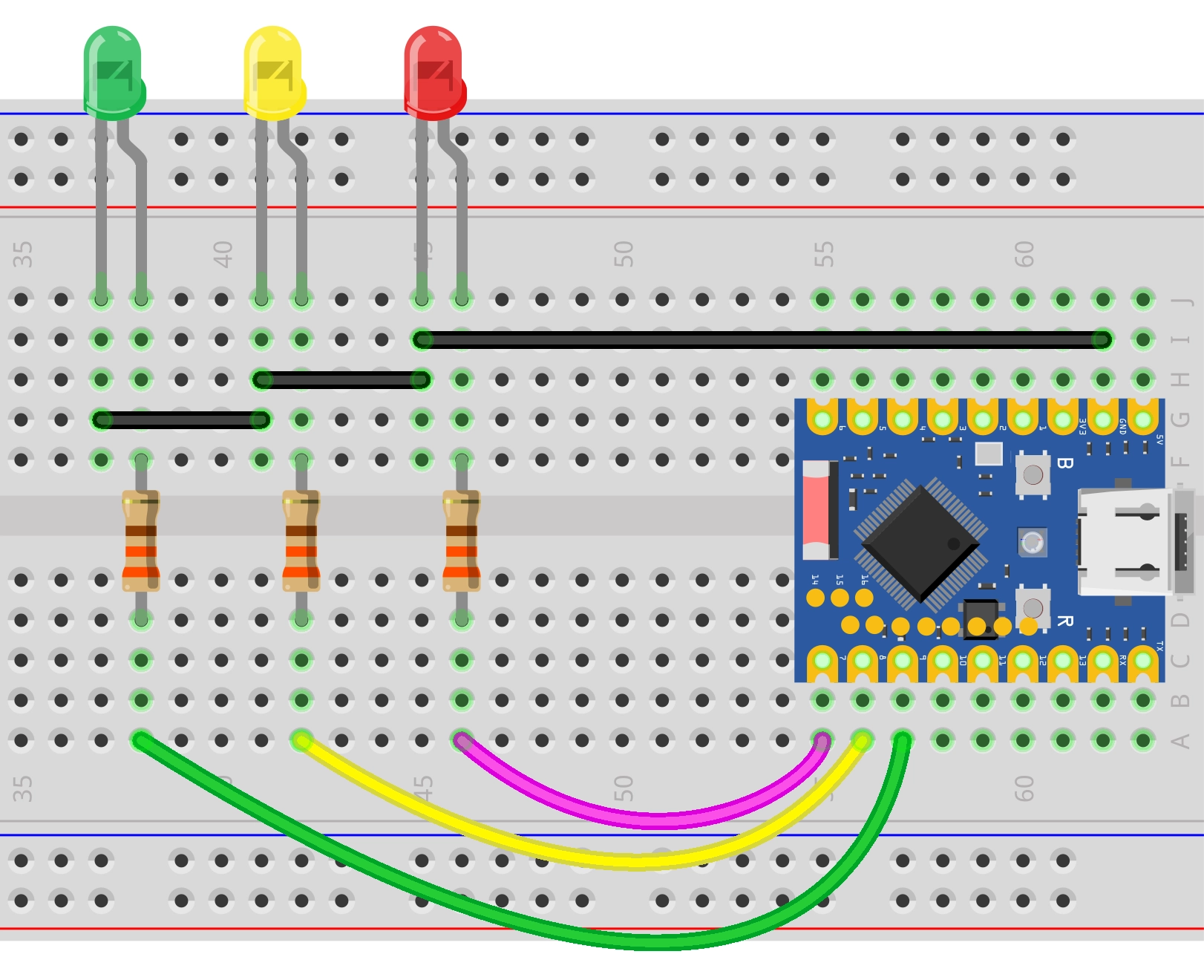
Hardware Connection
The components required are:
- LED * 3
- 330Ω resistor * 3
- Breadboard * 1
- Wire
- ESP32 development board
Connect the circuit according to the wiring diagram below:
ESP32-S3-Zero Pinout Diagram

Code Implementation
/*
  Traffic Light Simulation

   Simulates a traffic light system with red, green, and blinking yellow lights.
  The current state is printed to the serial monitor.

  Circuit Connection:
  - Red LED connected to pin 7
  - Yellow LED connected to pin 8
  - Green LED connected to pin 9

  Wulu (Waveshare Team)
*/

// Pin Definitions
const int redPin = 7;
const int yellowPin = 8;
const int greenPin = 9;

// Timing Definitions (unit: milliseconds)
const unsigned long redDuration = 10000;    // Red light duration
const unsigned long greenDuration = 8000;   // Green light duration
const unsigned long yellowDuration = 3000;  // Total yellow light duration
const unsigned long blinkInterval = 500;    // Blink interval

void setup() {
  // Initialize serial communication
  Serial.begin(115200);

  Serial.println("Traffic light simulation program started...");
  Serial.print("Current configuration: Red=");
  Serial.print(redDuration / 1000);
  Serial.print("s, Green=");
  Serial.print(greenDuration / 1000);
  Serial.print("s, Yellow=");
  Serial.println(yellowDuration / 1000);

  // Configure LED pins as output mode
  pinMode(redPin, OUTPUT);
  pinMode(yellowPin, OUTPUT);
  pinMode(greenPin, OUTPUT);
}

// Helper function: Turn off all lights
void allLightsOff() {
  digitalWrite(redPin, LOW);
  digitalWrite(yellowPin, LOW);
  digitalWrite(greenPin, LOW);
}

void loop() {
  // ---Green Light Phase ---
  Serial.println("Status: Green Light ON");
  allLightsOff();                // Make sure to start with a clean state
  digitalWrite(greenPin, HIGH);
  delay(greenDuration);

  // --- Yellow Blinking Phase ---
  Serial.println("Status: Yellow Light Blinking");
  digitalWrite(greenPin, LOW);

  // Calculate the number of blinks
  // A complete cycle consists of "on" and "off" and lasts for blinkInterval * 2
  int numBlinks = yellowDuration / (blinkInterval * 2);

  // Ensure at least one blink even if the duration is very short
  if (numBlinks == 0) {
    numBlinks = 1;
  }

  for (int i = 0; i < numBlinks; i++) {
    digitalWrite(yellowPin, HIGH);
    delay(blinkInterval);
    digitalWrite(yellowPin, LOW);
    delay(blinkInterval);
  }

  // --- Red Light Phase ---
  Serial.println("Status: Red Light ON");
  // Yellow and green lights are already off, directly turn on the red light
  digitalWrite(redPin, HIGH);
  delay(redDuration);
}
Code Analysis
-
Constant Definitions:
redPin,yellowPin,greenPin: Defines the GPIO pin numbers connected to the LEDs.redDuration,greenDuration,yellowDuration: Defines the duration each light stays on (unit: milliseconds).。blinkInterval: Defines the interval time for the yellow light blinking.
-
Initialization (
setup):Serial.begin(115200): Initializes serial communication with a baud rate of 115200, used to view the program status in the serial monitor.pinMode(pin, OUTPUT): Configures the pins connected to the LEDs as output mode to control the LED state (ON/OFF).
-
Helper Function (
allLightsOff):- This is a custom function used to set all LED pins to
LOW, turning off all lights. This helps ensure that no lights remain on before switching states.
- This is a custom function used to set all LED pins to
-
Main Loop (
loop):- Green Light Phase: First, call
allLightsOff()to turn off all lights, then turn on the green light (digitalWrite(greenPin, HIGH)) and hold forgreenDurationmilliseconds. - Yellow Blinking Phase:
- Turn off the green light.
- Calculate the number of blinks:
numBlinks = yellowDuration / (blinkInterval * 2). - Use a
forloop to control the yellow light alternating between ON and OFF (HIGH->delay->LOW->delay).
- Red Light Phase: Turn on the red light (
digitalWrite(redPin, HIGH)) and hold forredDurationmilliseconds.
- Green Light Phase: First, call