Example: Digital Output Control via GPIO
The core logic of this tutorial applies to all ESP32 boards, but all the operation steps are explained using the example of the Waveshare ESP32-S3-Zero mini development board. If you are using a development board of another model, please modify the corresponding settings according to the actual situation.
This tutorial will introduce how to use the Espressif ESP-IDF framework to control digital output via GPIO, enabling you to turn an LED on and off.
1. GPIO
The general steps for controlling digital output using GPIO in ESP-IDF are as follows:
-
Include Header File
First, include the GPIO driver header file:
#include "driver/gpio.h"And add the dependency (e.g.,
REQUIRES esp_driver_gpio) inCMakeLists.txt. -
Configure GPIO
Configure the GPIO for output mode. This can be done by initializing a
gpio_config_tstructure, for example:gpio_config_t io_conf = {.pin_bit_mask = (1ULL << GPIO_NUM_7), // Select the GPIO to configure.mode = GPIO_MODE_OUTPUT, // Set as output mode.pull_up_en = GPIO_PULLUP_DISABLE, // Disable pull-up.pull_down_en = GPIO_PULLDOWN_DISABLE, // Disable pull-down.intr_type = GPIO_INTR_DISABLE // Disable interrupt};gpio_config(&io_conf); -
Set Output Level
Use
gpio_set_levelto control the GPIO output level (high or low):gpio_set_level(GPIO_NUM_7, 1); // Output high levelgpio_set_level(GPIO_NUM_7, 0); // Output low level -
(Optional) Reset Pin
You can use
gpio_reset_pin(GPIO_NUM_7);to reset the pin to its default state (e.g., high impedance). This is useful before dynamically changing pin functions or entering low-power modes.
2. Example Project
This example demonstrates how to configure a GPIO pin for digital output mode and control it to cycle between high and low levels, achieving periodic blinking of an LED.
2.1 Circuit Assembly
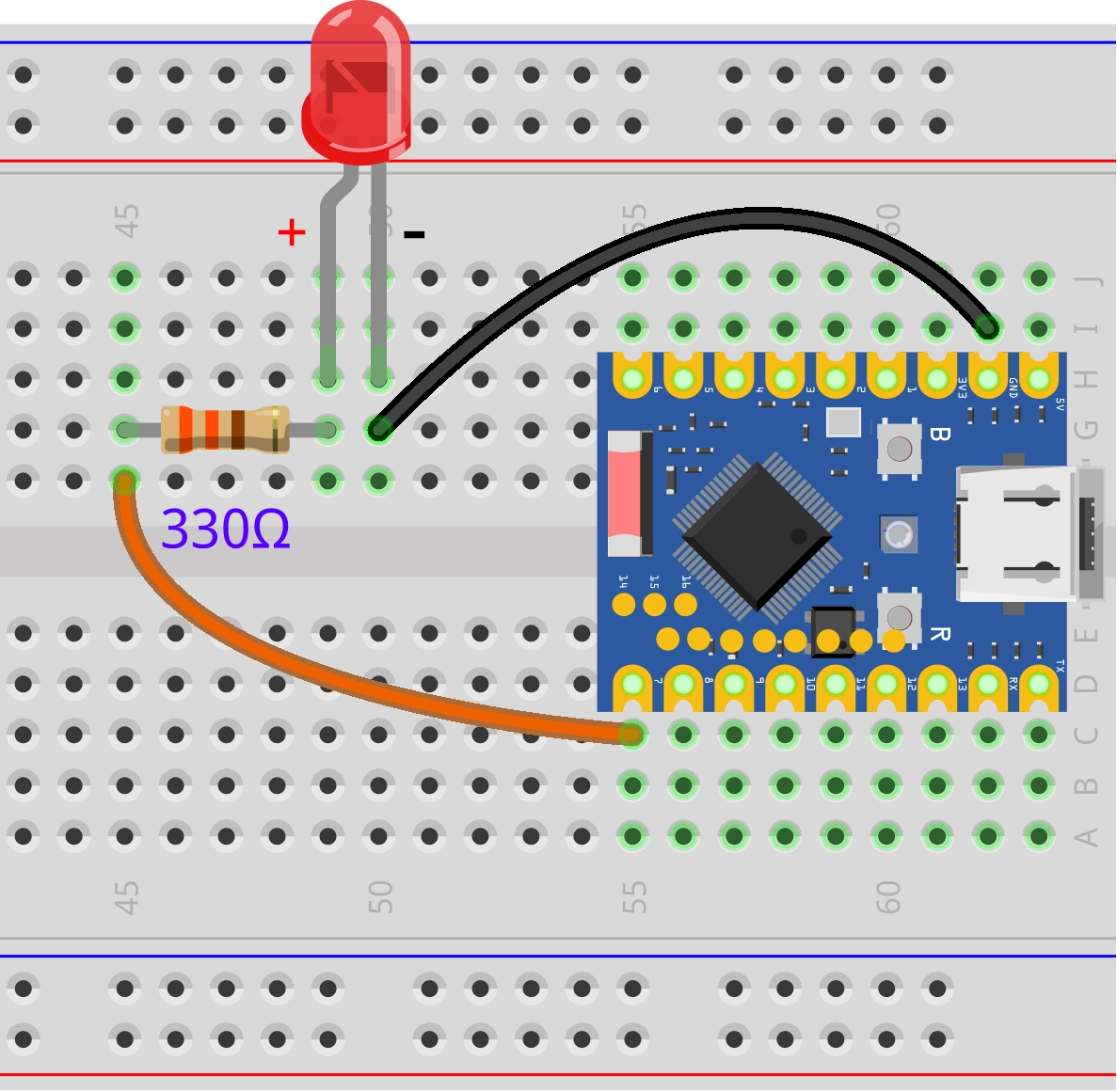
Components required:
- LED * 1
- 330Ω resistor * 1
- Breadboard * 1
- Wires
- ESP32 development board (Waveshare ESP32-S3-Zero Mini Development Board)
Connect the circuit according to the wiring diagram below:
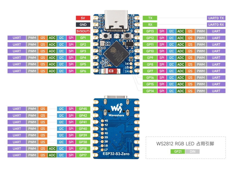
ESP32-S3-Zero Pinout Diagram
2.2 Create Project
-
Create a Project. If you are unsure how to do this, please refer to Create a Project from a Template.
-
Check the GPIO API Reference. Follow the instructions in the documentation to complete the following steps.
First, include the header file in main.c:
#include "driver/gpio.h"
Then, declare the esp_driver_gpio component in main/CMakeLists.txt:
idf_component_register(SRCS "main.c"
                      INCLUDE_DIRS "."
                      REQUIRES esp_driver_gpio)
2.3 Example Code
#include "driver/gpio.h"
#include "freertos/FreeRTOS.h"
#include "freertos/task.h"
#include "esp_log.h"

static const char *TAG = "example";

static const gpio_num_t GPIO_OUTPUT_LED = GPIO_NUM_7;

void app_main(void)
{
    gpio_config_t io_conf = {
        .pin_bit_mask = (1ULL << GPIO_OUTPUT_LED),  // Select the GPIO to configure
        .mode = GPIO_MODE_OUTPUT,              // Set as output mode
        .pull_up_en = GPIO_PULLUP_DISABLE,     // Disable pull-up
        .pull_down_en = GPIO_PULLDOWN_DISABLE, // Disable pull-down
        .intr_type = GPIO_INTR_DISABLE         // Disable interrupt
    };
    gpio_config(&io_conf);

    while (1) {
        // Set GPIO to high level
        ESP_LOGI(TAG, "Turn the LED on");
        gpio_set_level(GPIO_OUTPUT_LED, 1);
        vTaskDelay(pdMS_TO_TICKS(1000)); // Delay 1 second

        // Set GPIO to low level
        ESP_LOGI(TAG, "Turn the LED off");
        gpio_set_level(GPIO_OUTPUT_LED, 0);
        vTaskDelay(pdMS_TO_TICKS(1000)); // Delay 1 second
    }
}
2.4 Build and Flash
-
Configure Flash Options
Firstly, before building and flashing, please make sure to check and set the correct target device, serial port, and flashing method. Refer to Section 2 Run Demo - 1.3 Configure the Project.

-
Click
 to automatically perform the build, flash, and monitor steps in sequence with one click.
 -
After flashing is complete, you will see the LED on the development board start blinking. At the same time, the serial monitor will start and output the following log information:
I (256) main_task: Started on CPU0I (266) main_task: Calling app_main()I (266) example: Turn the LED onI (1266) example: Turn the LED offI (2266) example: Turn the LED onI (3266) example: Turn the LED offI (4266) example: Turn the LED onI (5266) example: Turn the LED off...
2.5 Code Analysis
The core of this example code is configuring a GPIO pin for output mode and alternately setting its level to high and low within an infinite loop, thereby achieving the blinking effect of an LED.
-
Include Header Files
#include "driver/gpio.h"#include "freertos/FreeRTOS.h"#include "freertos/task.h"#include "esp_log.h"driver/gpio.h: The ESP-IDF GPIO driver header file, providing all necessary function and type definitions for configuring and operating GPIO, such asgpio_config()andgpio_set_level().freertos/FreeRTOS.handfreertos/task.h: Core FreeRTOS header files. Here, they are mainly used to call thevTaskDelay()function for precise and efficient delays, a standard practice in real-time operating systems.esp_log.h: ESP-IDF's logging library for printing information to the serial monitor, facilitating debugging and observation of the program's status.
-
Define GPIO Pin
static const gpio_num_t GPIO_OUTPUT_LED = GPIO_NUM_7;- This line of code defines a constant
GPIO_OUTPUT_LEDto represent the GPIO pin number to which the LED is connected. gpio_num_tis an enumeration type used in ESP-IDF to represent GPIO numbers.GPIO_NUM_7is one of the values in this enumeration, representing the general-purpose I/O pin numbered 7 (GPIO7). For readability, it is recommended to useGPIO_NUM_7instead of directly writing the literal value7.
noteThe availability and limitations of GPIO7 vary across different chips. Please check the pin definitions of the development board you are using.
- This line of code defines a constant
-
Configure GPIO
gpio_config_t io_conf = {.pin_bit_mask = (1ULL << GPIO_OUTPUT_LED), // Select the GPIO to configure.mode = GPIO_MODE_OUTPUT, // Set as output mode.pull_up_en = GPIO_PULLUP_DISABLE, // Disable pull-up.pull_down_en = GPIO_PULLDOWN_DISABLE, // Disable pull-down.intr_type = GPIO_INTR_DISABLE // Disable interrupt};gpio_config(&io_conf);- We first create and initialize a
gpio_config_tstructure namedio_conf, which acts like a "configuration package" containing all the necessary settings. .pin_bit_mask: This is a bit mask used to specify which GPIO pin(s) to configure. Each bit corresponds to a GPIO number.1ULL: Represents the number 1 as a 64-bit unsigned long long integer. In binary, it is0x00...0001.<<: The left-shift operator in C.1ULL << Nmeans shifting the binary representation of this number 1 to the left by N positions.- In this example,
GPIO_OUTPUT_LEDhas the value7, so1ULL << 7shifts0x00...0001left by 7 bits, resulting in0x00...10000000(i.e., bit 7 is set to 1, all others are 0). This result is the "mask". Thegpio_config()function checks each bit of this mask; if a bit is 1, it applies the configuration to the corresponding GPIO pin.
.mode = GPIO_MODE_OUTPUT: Sets the pin mode to digital output..pull_up_enand.pull_down_en: Disable internal pull-up and pull-down resistors. For simple push-pull output scenarios like driving an LED, they are usually not needed..intr_type = GPIO_INTR_DISABLE: Disables the interrupt function because we are only performing output operations and do not need to respond to external signals.- Finally, the
gpio_config(&io_conf)function is called to apply this configuration to the specified GPIO pin.
tipThere are two main ways to configure GPIO:
-
Using the
gpio_config_tStructure (Recommended): This is the most common and efficient method. You can pack parameters like the pin bit mask, I/O mode, and pull-up/pull-down settings into a singlegpio_config_tstructure. Then, just one call togpio_config()configures one or multiple GPIO pins simultaneously. -
Using Independent Functions: ESP-IDF also provides a series of independent API functions, such as
gpio_set_direction()andgpio_set_pull_mode(), for individually setting specific properties of a pin. This approach is more flexible, suitable for dynamic modifications at runtime or simple single-property settings.For the examples in this tutorial, if you configure using a standalone function, the code is as follows:
gpio_reset_pin(GPIO_OUTPUT_LED); // Reset the pingpio_set_direction(GPIO_OUTPUT_LED, GPIO_MODE_OUTPUT); // Set the pin as output mode
- We first create and initialize a
-
Main Loop: Controlling LED Blink
while (1) {// Set GPIO to high levelESP_LOGI(TAG, "Turn the LED on");gpio_set_level(GPIO_OUTPUT_LED, 1);vTaskDelay(pdMS_TO_TICKS(1000)); // Delay 1 second// Set GPIO to low levelESP_LOGI(TAG, "Turn the LED off");gpio_set_level(GPIO_OUTPUT_LED, 0);vTaskDelay(pdMS_TO_TICKS(1000)); // Delay 1 second}while (1)creates an infinite loop, ensuring theapp_mainfunction does not exit and the code inside runs continuously.gpio_set_level(GPIO_OUTPUT_LED, 1): Calls this function to set the level of GPIO 7 to high (typically 3.3V). According to the circuit connection, this turns the LED on.gpio_set_level(GPIO_OUTPUT_LED, 0): Sets the level of GPIO 7 to low (0V), thereby turning the LED off.vTaskDelay(pdMS_TO_TICKS(1000)): This is a delay function provided by FreeRTOS. It suspends the current task (the main task) for the specified duration. Unlike a simple busy wait (like aforloop),vTaskDelayyields CPU usage, allowing other tasks to run, making it a very efficient way to delay.pdMS_TO_TICKS(1000)is a macro that converts 1000 milliseconds (1 second) into the number of "system ticks" used by the FreeRTOS scheduler.