Working with Arduino
This chapter contains the following sections. Please read as needed:
Arduino Getting Started
New to Arduino ESP32 development and looking for a quick start? We have prepared a comprehensive Getting Started Tutorial for you.
- Section 0: Getting to Know ESP32
- Section 1: Installing and Configuring Arduino IDE
- Section 2: Arduino Basics
- Section 3: Digital Output/Input
- Section 4: Analog Input
- Section 5: Pulse Width Modulation (PWM)
- Section 6: Serial Communication (UART)
- Section 7: I2C Communication
- Section 8: SPI Communication
- Section 9: Wi-Fi Basics
- Section 10: Web Server
- Section 11: Bluetooth
- Section 12: LVGL GUI Development
- Section 13: Comprehensive Project
Note: This tutorial uses the ESP32-S3-Zero as a reference example, and all hardware code is based on its pinout. Before you start, we recommend checking the pinout of your development board to ensure the pin configuration is correct.
Setting Up the Development Environment
1. Installing and Configuring the Arduino IDE
For the ESP32-S3-RLCD-4.2 development board, the Arduino IDE requires the installation of arduino-esp32 v3.3.0 or higher.
Please refer to the tutorial Installing and Configuring Arduino IDE to download and install the Arduino IDE and add ESP32 support.
2. Installing Libraries
- When installing Arduino libraries, there are typically two methods: Install Online and Install Offline. If the library installation requires Install Offline, you must use the provided library file.
- For most libraries, users can easily search for and install them via the Arduino IDE's online Library Manager. However, some open-source or custom libraries are not synchronized to the Arduino Library Manager and therefore cannot be found through online search. In this case, users can only install these libraries manually via offline methods.
- The example program package for the ESP32-S3-RLCD-4.2 development board can be downloaded from here. The
Arduino\librariesdirectory within the package already contains all the library files required for this tutorial.
| Library/File Name | Description | Version | Installation Method |
|---|---|---|---|
| LVGL | Graphics Library | v8.3.11/v9.3.0 | "Install Offline" |
| SensorLib | Sensor library | v0.3.1 | "Install Online" or "Install Offline" |
There are strong dependencies between versions of LVGL and its driver libraries. For example, a driver written for LVGL v8 may not be compatible with LVGL v9. To ensure that the examples can be reproduced reliably, it is recommended to use the specific versions listed in the table above. Mixing different versions of libraries may lead to compilation failures or runtime errors.
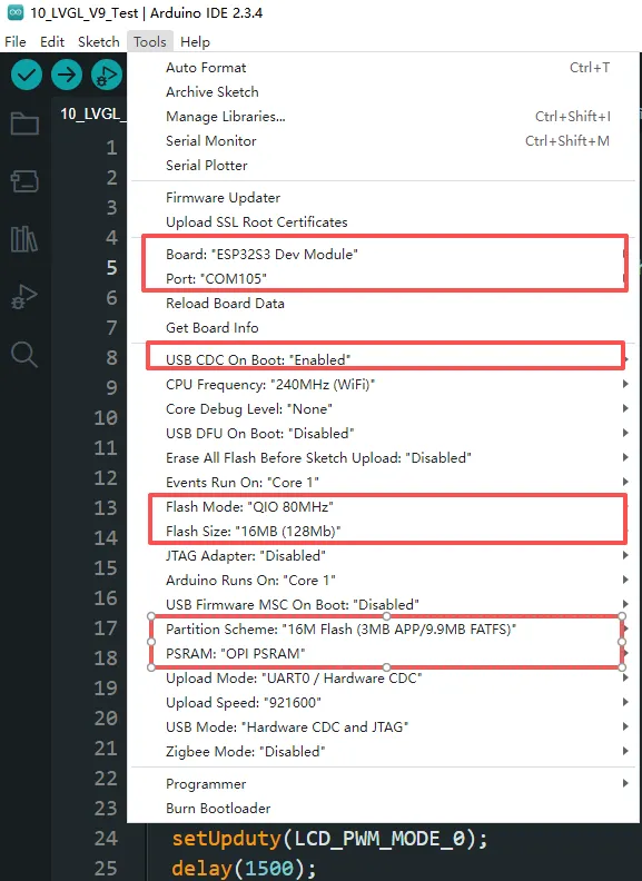
3. Arduino Project Parameter Settings
Example
The Arduino examples are located in the Arduino/examples directory of the example package.
| Example | Basic Program Description | Dependency Library |
|---|---|---|
| 01_WIFI_AP | Set to AP mode to obtain the IP address of the access device | - |
| 02_WIFI_STA | Set to STA mode to connect to Wi-Fi and obtain an IP address | - |
| 03_ADC_Test | Get the voltage value of the lithium battery | - |
| 04_I2C_PCF85063 | Print real-time time of RTC chip | SensorLib |
| 05_I2C_SHTC3 | Print temperature and humidity sensor data | - |
| 06_SD_Card | Load and display TF card information | - |
| 07_Audio_Test | Play the sound recorded by the microphone through the speaker | LVGL V8.3.11 |
| 08_LVGL_V8_Test | LVGLV8 example | LVGL V8.3.11 |
| 09_LVGL_V9_Test | LVGLV9 example | LVGL V9.3.0 |
| 10_U8G2_Test | U8G2 porting example | U8G2 master |
01_WIFI_AP
Example Description
- This example can set the development board as a hotspot, allowing phones or other devices in STA mode to connect to the development board.
Hardware Connection
- Connect the board to the computer using a USB cable.
Code Analysis
*In the file 01_WIFI_AP.ino, find ssid and password, then a phone or other device in STA mode can connect to the development board using these ssid and password.
const char *ssid = "ESP32_AP";
const char *password = "12345678";
Operation Result
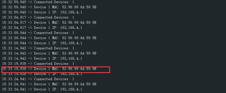
-
After flashing the program, open the Serial Terminal. If a device successfully connects to the hotspot, the MAC address of that device will be output, as shown:
02_WIFI_STA
Example Description
- This example configures the development board as a STA device to connect to a router, thereby accessing the system network.
Hardware Connection
- Connect the board to the computer using a USB cable.
Code Analysis
-
In the file
02_WIFI_STA.ino, findssidandpassword, then modify them to the SSID and Password of an available router in your current environment.const char *ssid = "you_ssid";const char *password = "you_password";
Operation Result
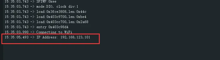
-
After flashing the program, open the Serial Terminal. If the device successfully connects to the hotspot, the obtained IP address will be output, as shown in the figure:
03_ADC_Test
Example Description
- The analog voltage connected through the GPIO is converted to digital by the ADC, and then the actual lithium battery voltage is calculated and printed to the terminal.
Hardware Connection
- Connect the board to the computer using a USB cable.
Code Analysis
Adc_PortInit(void): Initializes ADC1, including creating an ADC one-time trigger unit and configuring channel 3 for ADC1float Adc_GetBatteryVoltage(int *data): Reads the value from ADC1 channel 3 and returns the actual voltage value.uint8_t Adc_GetBatteryLevel(void): Returns the battery percentage.void Adc_LoopTask(void *arg): Creates an ADC task that reads the ADC value and prints it to the serial port every second.
Operation Result
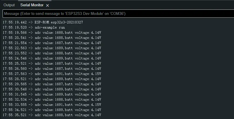
-
After the program is compiled and downloaded, you can view the printed ADC values and voltage output by opening the Serial Monitor, as shown in the following image:
04_I2C_PCF85063
Example Description
- Through the I2C protocol, initialize the PCF85063 chip, set the time, and then periodically read the time and print it to the terminal
Hardware Connection
- Connect the board to the computer using a USB cable.
Code Analysis
I2cMasterBus I2cbus(14,13,0);          // Initialize I2C bus
void setup() {
Serial.begin(115200);
delay(1000);
Serial.printf("rtc-example run \n");
Rtc_Setup(&I2cbus, 0x51);              // Initialize RTC, set RTC slave address to 0x51
Rtc_SetTime(2025, 9, 9, 20, 15, 30);   // Set RTC time
}

void loop() {
  rtcTimeStruct_t rtcData;
  Rtc_GetTime(&rtcData);              // Get the real-time clock (RTC) time
  Serial.printf("%d/%d/%d %02d:%02d:%02d \n",
                rtcData.year, rtcData.month, rtcData.day, rtcData.hour, rtcData.minute,
                rtcData.second);
  delay(1000);
}
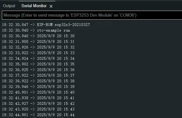
Operation Result
-
After the program is compiled and downloaded, open the serial port monitoring to see the RTC time of the printout, as shown in the following figure:
05_I2C_SHTC3
Example Description
- Initialize the SHTC3 chip through the I2C protocol, and then print the temperature and humidity information read every 1 second to the terminal
Hardware Connection
- Connect the board to the computer using a USB cable.
Code Analysis
I2cMasterBus I2cbus(14,13,0);
Shtc3Port *shtc3port = NULL;

void setup() {
  Serial.begin(115200);
  delay(1000);
  Serial.printf("shtc3-example run \n");
  shtc3port = new Shtc3Port(I2cbus);         // Initialize SHTC3
}

void loop() {
  float rh,temp;
  shtc3port->Shtc3_ReadTempHumi(&temp,&rh);  // Get temperature and humidity data
  Serial.printf("RH:%.2f%%,Temp:%.2f° \n",rh,temp);
  delay(1000);
}
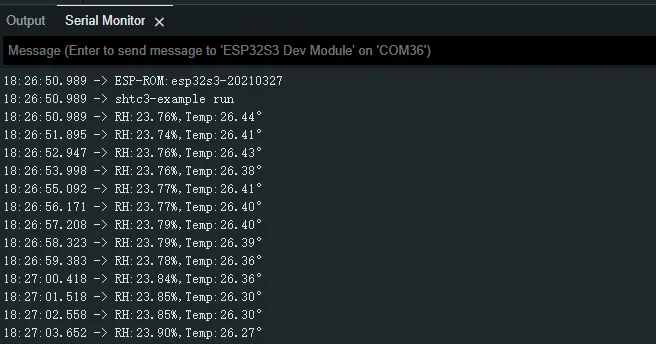
Operation Result
-
Open the serial port monitor, you can see the printed temperature and humidity data, as shown in the figure below:
06_SD_Card
Example Description
- Drive the TF card through SDMMC, and print the TF card information to the terminal after successfully mounting.
Hardware Connection
- Install a FatFs-formatted TF card into the board before powering on
Code Analysis
#define sdcard_write_Test

CustomSDPort *sdcardPort = NULL;

void setup()
{
  Serial.begin(115200);
  delay(2000);
  sdcardPort = new CustomSDPort("/sdcard");  // Initialize SDMMC driver
}

uint32_t value = 1;
char sdcard_read[45] = {""};
char sdcard_write[45] = {""};

void loop()
{
#ifdef sdcard_write_Test      // Test the TF card read/write functionality
  snprintf(sdcard_write,45,"sdcard_writeTest : %ld \n",value);
  sdcardPort->SDPort_WriteFile("/sdcard/writeTest.txt",sdcard_write,strlen(sdcard_write));
  vTaskDelay(pdMS_TO_TICKS(500));
  sdcardPort->SDPort_ReadFile("/sdcard/writeTest.txt",(uint8_t *)sdcard_read,NULL);
  Serial.printf("read data:%s\n",sdcard_read);
  vTaskDelay(pdMS_TO_TICKS(500));
  value++;
#endif
}
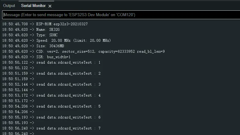
Operation Result
-
Click on the serial port monitoring device, you can see the output information of the TF card, as shown in the figure below:
07_Audio_Test
Example Description
- Demonstrates how to get data from the microphone and then play it through the speaker
Hardware Connection
- Connect the board to the computer using a USB cable.
Code Analysis
CodecPort_SetInfo("es8311 & es7210",1,16000,2,16): Sets the sampling rate, number of channels, and bit depth of the Codec chip.CodecPort_SetSpeakerVol(100): Set the playback gain to 100.CodecPort_SetMicGain(35): Set the microphone gain to 35.Codec_LoopTask(void *arg): Codec task, which implements recording, playback, and other functions.
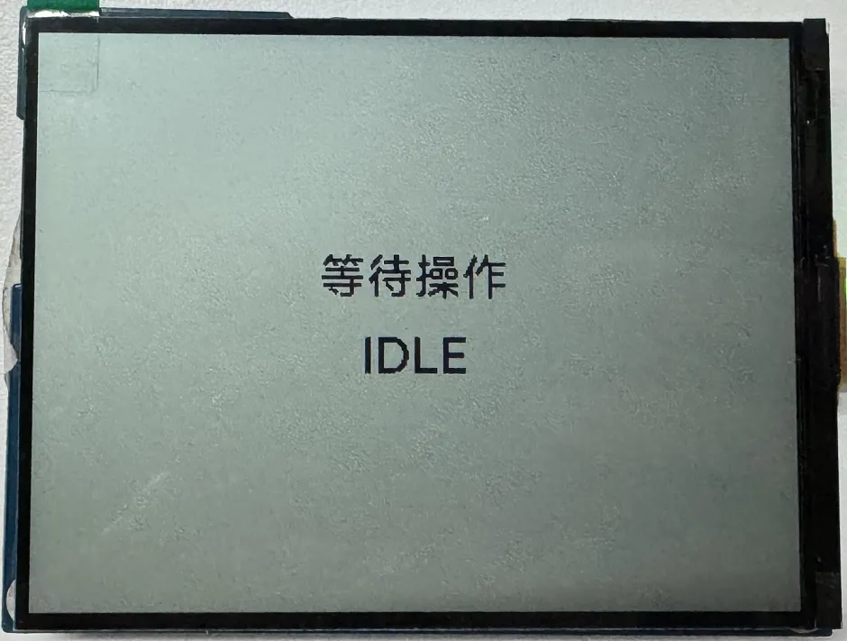
Operation Result
-
After the program is flashed, as shown in the figure:
 tip
tip- Double-click the BOOT button to enter recording mode, speak into the MIC, and it will automatically end after 3 seconds
- Click the BOOT button to play the sound you just recorded
- Double-click the KEY button to play a piece of music
- Click the KEY button to interrupt music playback
08_LVGL_V8_Test
Example Description
- Demonstrates how to display images using LVGL V8, helping users get started quickly with LVGL V8.
Hardware Connection
- Connect the board to the computer using a USB cable.
Code Analysis
/*Create an IMG1 widget */
ui->screen_img_1 = lv_img_create(ui->screen);
lv_obj_add_flag(ui->screen_img_1, LV_OBJ_FLAG_CLICKABLE);
lv_img_set_src(ui->screen_img_1, &_ein_alpha_400x300);
lv_img_set_pivot(ui->screen_img_1, 50,50);
lv_img_set_angle(ui->screen_img_1, 0);
lv_obj_set_pos(ui->screen_img_1, 0, 0);
lv_obj_set_size(ui->screen_img_1, 400, 300);
/*Create an IMG2 widget */
ui->screen_img_2 = lv_img_create(ui->screen);
lv_obj_add_flag(ui->screen_img_2, LV_OBJ_FLAG_CLICKABLE);
lv_img_set_src(ui->screen_img_2, &_2_alpha_400x300);
lv_img_set_pivot(ui->screen_img_2, 50,50);
lv_img_set_angle(ui->screen_img_2, 0);
lv_obj_set_pos(ui->screen_img_2, 0, 0);
lv_obj_set_size(ui->screen_img_2, 400, 300);
lv_obj_add_flag(ui->screen_img_2, LV_OBJ_FLAG_HIDDEN);
Operation Result
-
After the program is flashed, it is displayed alternately at intervals of 1.5 seconds, as shown in the figure:

09_LVGL_V9_Test
Example Description
- Demonstrates how to display images using LVGL V9, helping users get started quickly with LVGL V9.
Hardware Connection
- Connect the board to the computer using a USB cable.
Code Analysis
/*Create an IMG1 widget */
ui->screen_img_1 = lv_image_create(ui->screen);
lv_obj_set_pos(ui->screen_img_1, 0, 0);
lv_obj_set_size(ui->screen_img_1, 400, 300);
lv_obj_add_flag(ui->screen_img_1, LV_OBJ_FLAG_CLICKABLE);
lv_image_set_src(ui->screen_img_1, &_ein_RGB565A8_400x300);
lv_image_set_pivot(ui->screen_img_1, 50,50);
lv_image_set_rotation(ui->screen_img_1, 0);
/*Create an IMG2 widget */
ui->screen_img_2 = lv_image_create(ui->screen);
lv_obj_set_pos(ui->screen_img_2, 0, 0);
lv_obj_set_size(ui->screen_img_2, 400, 300);
lv_obj_add_flag(ui->screen_img_2, LV_OBJ_FLAG_HIDDEN);
lv_obj_add_flag(ui->screen_img_2, LV_OBJ_FLAG_CLICKABLE);
lv_image_set_src(ui->screen_img_2, &_2_RGB565A8_400x300);
lv_image_set_pivot(ui->screen_img_2, 50,50);
lv_image_set_rotation(ui->screen_img_2, 0);
Operation Result
-
After the program is flashed, it is displayed alternately at intervals of 1.5 seconds, as shown in the figure:

10_U8G2_Test
Example Description
- Completes the porting of the U8G2 library, supporting fast screen refreshing, helping users precisely target product functions and display effects.
Hardware Connection
- Connect the board to the computer using a USB cable.
Code Analysis
u8g2_clearBuffer();     // Clear screen
u8g2_setFont();         // Set font
u8g2_drawStr();         // Draw counter and text
u8g2_drawFrame();       // Draw border
u8g2_drawHLine();       // Draw bottom separator line
u8g2_sendBuffer();      // Refresh screen
u8g2_drawPixel(x, y);   // Draw a pixel
u8g2_drawLine(x1, y1, x2, y2);    // Draw an arbitrary line
u8g2_drawBox(x, y, w, h);         // Filled rectangle
u8g2_drawCircle(x, y, r);         // Hollow circle
u8g2_drawDisc(x, y, r);           // Filled circle
u8g2_drawTriangle(x0, y0, x1, y1, x2, y2); // Filled triangle
u8g2_drawXBMP(x, y, w, h, bitmap); // Draw XBM format monochrome bitmap
u8g2_drawBitmap(x, y, cnt, h, bitmap); // Draw U8g2 bitmap
Operation Result
-
After the program is flashed, the screen displays as shown:
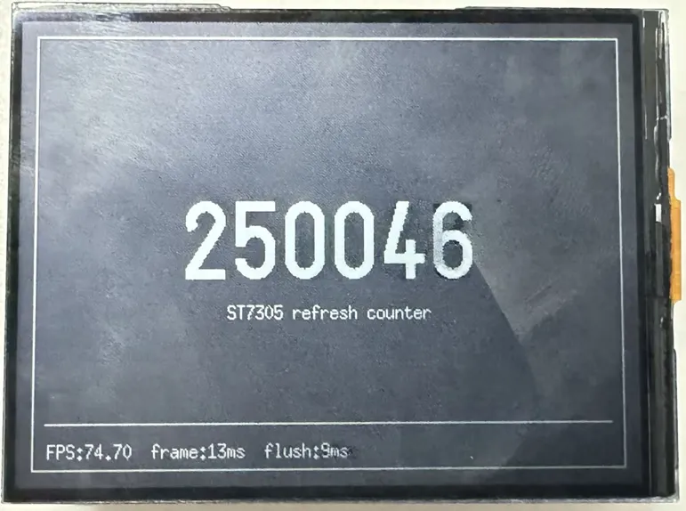 tip
tip- FPS can reach 74 frames, suitable for fast-refresh applications.