ESP-IDF
This chapter contains the following sections. Please read as needed:
ESP-IDF Getting Started
New to ESP32 ESP-IDF development and looking to get started quickly? We have prepared a general Getting Started Tutorial for you.
- Section 1: Environment Setup
- Section 2: Running Examples
- Section 3: Creating a Project
- Section 4: Using Components
- Section 5: Debugging
- Section 6: FreeRTOS
- Section 7: Peripherals
- Section 8: Wi-Fi Programming
- Section 9: BLE Programming
Please Note: This tutorial uses the ESP32-S3-Zero as a teaching example, and all hardware code is based on its pinout. Before you start, it is recommended that you check the pinout of your development board to ensure the pin configuration is correct.
Setting Up the Development Environment
For the ESP32-S3-RLCD-4.2 development board, ESP-IDF version V5.5.0 or above is required.
The following guide uses Windows as an example, demonstrating development using VS Code + the ESP-IDF extension. macOS and Linux users should refer to the official documentation.
The screenshots in this section use ESP-IDF V5.5.2 as an example. When installing, please select the ESP-IDF version that matches your board's example.
Install the ESP-IDF Development Environment
-
Download the installation manager from the ESP-IDF Installation Manager page. This is Espressif's latest cross-platform installer. The following steps demonstrate how to use its offline installation feature.
Click the Offline Installer tab on the page, then select Windows as the operating system and the ESP-IDF version you need (the version shown in the screenshot is for reference only — choose the version that fits your actual needs).

After confirming your selection, click the download button. The browser will automatically download two files: the ESP-IDF Offline Package (.zst) and the ESP-IDF Installer (.exe).

Please wait for both files to finish downloading.
-
Once the download is complete, double-click to run the ESP-IDF Installer (eim-gui-windows-x64.exe).
The installer will automatically detect if the offline package exists in the same directory. Click Install from archive.

Next, select the installation path. We recommend using the default path. If you need to customize it, ensure the path does not contain Chinese characters or spaces. Click Start installation to proceed.

-
When you see the following screen, the ESP-IDF installation is successful.

-
We recommend installing the drivers as well. Click Finish installation, then select Install driver.

Install Visual Studio Code and the ESP-IDF Extension
-
Download and install Visual Studio Code.
-
During installation, it is recommended to check Add "Open with Code" action to Windows Explorer file context menu to facilitate opening project folders quickly.
-
In VS Code, click the Extensions icon
 in the Activity Bar on the side (or use the shortcut Ctrl + Shift + X) to open the Extensions view.
 -
Enter ESP-IDF in the search box, locate the ESP-IDF extension, and click Install.

-
For ESP-IDF extension versions ≥ 2.0, the extension will automatically detect and recognize the ESP-IDF environment installed in the previous steps, requiring no manual configuration.
Example
The ESP-IDF examples are located in the ESP-IDF directory of the example package.
| Example | Basic Program Description | Dependency Library |
|---|---|---|
| 01_WIFI_AP | Set to AP mode to obtain the IP address of the access device | - |
| 02_WIFI_STA | Set to STA mode to connect to Wi-Fi and obtain an IP address | - |
| 03_ADC_Test | Get the voltage value of the lithium battery | - |
| 04_I2C_PCF85063 | Print real-time time of RTC chip | SensorLib |
| 05_I2C_SHTC3 | Print temperature and humidity sensor data | - |
| 06_SD_Card | Load and display TF card information | - |
| 07_Audio_Test | Play the sound recorded by the microphone through the speaker | LVGL V8.3.11 |
| 08_LVGL_V8_Test | LVGLV8 example | LVGL V8.3.11 |
| 09_LVGL_V9_Test | LVGLV9 example | LVGL V9.3.0 |
| 10_FactoryProgram | Comprehensive example | LVGL V8.3.11 |
| 11_U8G2_Test | U8G2 porting example | U8G2 master |
01_WIFI_AP
Example Description
- This example can set the development board as a hotspot, allowing phones or other devices in STA mode to connect to the development board.
Hardware Connection
- Connect the board to the computer using a USB cable.
Code Analysis
-
In the file
softap_example_main.c, findSSIDandPASSWORD, and then your phone or other device in STA mode can use the SSID and PASSWORD to connect to the development board.#define EXAMPLE_ESP_WIFI_SSID "waveshare_esp32"#define EXAMPLE_ESP_WIFI_PASSWORD "wav123456"
Operation Result
-
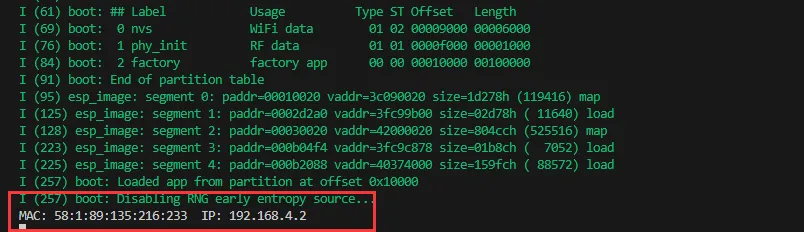
After flashing the program, open the Serial Terminal. If a device successfully connects to the hotspot, it will output the device's MAC address and IP address, as shown in the figure:
02_WIFI_STA
Example Description
- This example configures the development board as a STA device to connect to a router, thereby accessing the system network.
Hardware Connection
- Connect the board to the computer using a USB cable.
Code Analysis
-
In the file
esp_wifi_bsp.c, findssidandpassword, then modify them to the SSID and Password of an available router in your current environment.wifi_config_t wifi_config = {.sta = {.ssid = "PDCN",.password = "1234567890",},};
Operation Result
-
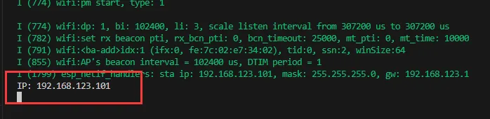
After flashing the program, open the Serial Terminal. If the device successfully connects to the hotspot, the obtained IP address will be output, as shown in the figure:
03_ADC_Test
Example Description
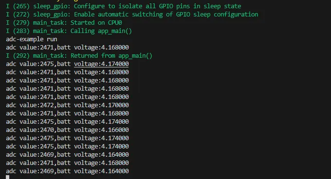
- The analog voltage connected through the GPIO is converted to digital by the ADC, and then the actual lithium battery voltage is calculated and printed to the terminal.
Hardware Connection
- Connect the board to the computer using a USB cable.
Code Analysis
Adc_PortInit(void): Initializes ADC1, including creating an ADC one-time trigger unit and configuring channel 3 for ADC1float Adc_GetBatteryVoltage(int *data): Reads the value from ADC1 channel 3 and returns the actual voltage value.uint8_t Adc_GetBatteryLevel(void): Returns the battery percentage.void Adc_LoopTask(void *arg): Creates an ADC task that reads the ADC value and prints it to the serial port every second.
Operation Result
-
After the program is compiled and downloaded, you can view the printed ADC values and voltage output by opening the Serial Monitor, as shown in the following image:
04_I2C_PCF85063
Example Description
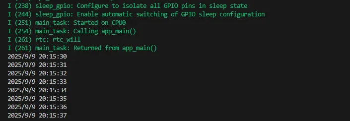
- Through the I2C protocol, initialize the PCF85063 chip, set the time, and then periodically read the time and print it to the terminal
Hardware Connection
- Connect the board to the computer using a USB cable.
Code Analysis
void Rtc_LoopTask(void *arg): Create an RTC task to implement the RTC function, read the clock of the RTC chip every 1 second, and then output it to the terminal.
Operation Result
-
After the program is compiled and downloaded, open the serial port monitoring to see the RTC time of the printout, as shown in the following figure:
05_I2C_STHC3
Example Description
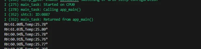
- Initialize the SHTC3 chip through the I2C protocol, and then print the temperature and humidity information read every 1 second to the terminal
Hardware Connection
- Connect the board to the computer using a USB cable.
Code Analysis
void Shtc3_LoopTask(void *arg): Create a SHTC3 sensor task that obtains temperature and humidity at intervals of 1 second.
Operation Result
-
Open the serial port monitor, you can see the printed temperature and humidity data, as shown in the figure below:
06_SD_Card
Example Description
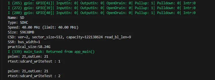
- Drive the TF card through SDMMC, and print the TF card information to the terminal after successfully mounting.
Hardware Connection
- Install a FatFs-formatted TF card into the board before powering on
Code Analysis
Fatfs_LoopTask(void *arg): A task to test TF card read and write functionality. You need to uncomment the#define sdcard_write_Testmacro definition.
Operation Result
-
Click on the serial port monitoring device, you can see the output information of the TF card, as shown in the figure below:
07_Audio_Test
Example Description
- Demonstrates how to get data from the microphone and then play it through the speaker
Hardware Connection
- Connect the board to the computer using a USB cable.
Code Analysis
CodecPort_SetInfo("es8311 & es7210",1,16000,2,16): Sets the sampling rate, number of channels, and bit depth of the Codec chip.CodecPort_SetSpeakerVol(100): Set the playback gain to 100.CodecPort_SetMicGain(35): Set the microphone gain to 35.Codec_LoopTask(void *arg): Codec task, which implements recording, playback, and other functions.
Operation Result
-
After the program is flashed, as shown in the figure:
 tip
tip- Double-click the BOOT button to enter recording mode, speak into the MIC, and it will automatically end after 3 seconds
- Click the BOOT button to play the sound you just recorded
- Double-click the KEY button to play a piece of music
- Click the KEY button to interrupt music playback
08_LVGL_V8_Test
Example Description
- Demonstrates how to display images using LVGL V8, helping users get started quickly with LVGL V8.
Hardware Connection
- Connect the board to the computer using a USB cable.
Code Analysis
/*Create an IMG1 widget */
ui->screen_img_1 = lv_img_create(ui->screen);
lv_obj_add_flag(ui->screen_img_1, LV_OBJ_FLAG_CLICKABLE);
lv_img_set_src(ui->screen_img_1, &_ein_alpha_400x300);
lv_img_set_pivot(ui->screen_img_1, 50,50);
lv_img_set_angle(ui->screen_img_1, 0);
lv_obj_set_pos(ui->screen_img_1, 0, 0);
lv_obj_set_size(ui->screen_img_1, 400, 300);
/*Create an IMG2 widget */
ui->screen_img_2 = lv_img_create(ui->screen);
lv_obj_add_flag(ui->screen_img_2, LV_OBJ_FLAG_CLICKABLE);
lv_img_set_src(ui->screen_img_2, &_2_alpha_400x300);
lv_img_set_pivot(ui->screen_img_2, 50,50);
lv_img_set_angle(ui->screen_img_2, 0);
lv_obj_set_pos(ui->screen_img_2, 0, 0);
lv_obj_set_size(ui->screen_img_2, 400, 300);
lv_obj_add_flag(ui->screen_img_2, LV_OBJ_FLAG_HIDDEN);
Operation Result
-
After the program is flashed, it is displayed alternately at intervals of 1.5 seconds, as shown in the figure:

09_LVGL_V9_Test
Example Description
- Demonstrates how to display images using LVGL V9, helping users get started quickly with LVGL V9.
Hardware Connection
- Connect the board to the computer using a USB cable.
Code Analysis
/*Create an IMG1 widget */
ui->screen_img_1 = lv_image_create(ui->screen);
lv_obj_set_pos(ui->screen_img_1, 0, 0);
lv_obj_set_size(ui->screen_img_1, 400, 300);
lv_obj_add_flag(ui->screen_img_1, LV_OBJ_FLAG_CLICKABLE);
lv_image_set_src(ui->screen_img_1, &_ein_RGB565A8_400x300);
lv_image_set_pivot(ui->screen_img_1, 50,50);
lv_image_set_rotation(ui->screen_img_1, 0);
/*Create an IMG2 widget */
ui->screen_img_2 = lv_image_create(ui->screen);
lv_obj_set_pos(ui->screen_img_2, 0, 0);
lv_obj_set_size(ui->screen_img_2, 400, 300);
lv_obj_add_flag(ui->screen_img_2, LV_OBJ_FLAG_HIDDEN);
lv_obj_add_flag(ui->screen_img_2, LV_OBJ_FLAG_CLICKABLE);
lv_image_set_src(ui->screen_img_2, &_2_RGB565A8_400x300);
lv_image_set_pivot(ui->screen_img_2, 50,50);
lv_image_set_rotation(ui->screen_img_2, 0);
Operation Result
-
After the program is flashed, it is displayed alternately at intervals of 1.5 seconds, as shown in the figure:
10_FactoryProgram
Example Description
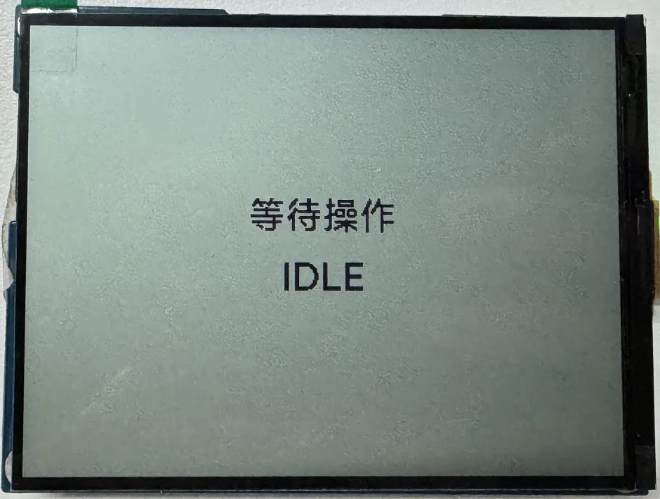
- The driver board integrates all hardware components and provides comprehensive examples, enabling users to quickly understand the product.
Hardware Connection
- Connect the board to the computer using a USB cable.
Code Analysis
sdcardPort = new CustomSDPort("/sdcard"); // Initialize sdcard
Adc_PortInit();                           // Initialize Adc
Custom_ButtonInit();                      // Initialize buttons
Rtc_Setup(&I2cbus,0x51);                  // Initialize RTC
Rtc_SetTime(2026,1,5,14,30,30);           // Set RTC time
shtc3port = new Shtc3Port(I2cbus);        // Initialize Shtc3
espwifi_init();                           // Initialize WiFi STA mode
CodecGroups = xEventGroupCreate();
codecport = new CodecPort(I2cbus,"S3_RLCD_4_2"); // Initialize Codec
codecport->CodecPort_SetInfo("es8311 & es7210",1,16000,2,16);
codecport->CodecPort_SetSpeakerVol(100);         // Set the speaker gain
codecport->CodecPort_SetMicGain(35);             // Set the microphone gain
Operation Result
-
After the program is flashed, the main interface is displayed, as shown in the figure:
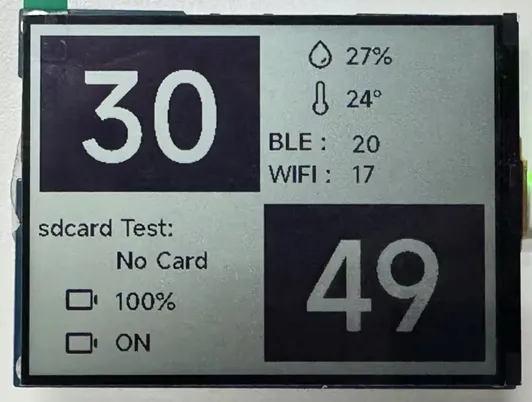 tip
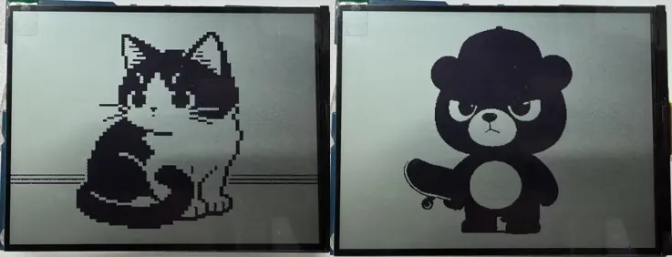
tip- Long press the KEY button to enter the image display interface
- Long press the BOOT button to enter the music playback interface
-
Image display interface, as shown in the figure:
 tip
tip- Long press the KEY button to return to the main interface
-
Music playback interface, as shown in the figure:
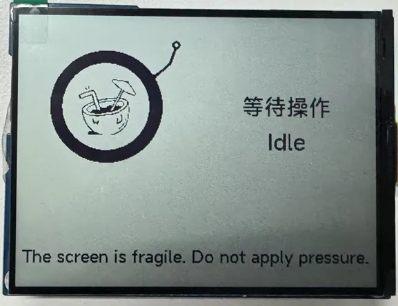 tip
tip- Double-click the BOOT button to enter recording mode, speak into the MIC, and it will automatically end after 3 seconds
- Click the BOOT button to play the sound you just recorded
- Double-click the KEY button to play a piece of music
- Click the KEY button to interrupt music playback
- Long press the BOOT button to go back to the interface
11_U8G2_Test
Example Description
- Completes the porting of the U8G2 library, supporting fast screen refreshing, helping users precisely target product functions and display effects.
Hardware Connection
- Connect the board to the computer using a USB cable.
Code Analysis
u8g2_clearBuffer();     // Clear screen
u8g2_setFont();         // Set font
u8g2_drawStr();         // Draw counter and text
u8g2_drawFrame();       // Draw border
u8g2_drawHLine();       // Draw bottom separator line
u8g2_sendBuffer();      // Refresh screen
u8g2_drawPixel(x, y);   // Draw a pixel
u8g2_drawLine(x1, y1, x2, y2);    // Draw an arbitrary line
u8g2_drawBox(x, y, w, h);         // Filled rectangle
u8g2_drawCircle(x, y, r);         // Hollow circle
u8g2_drawDisc(x, y, r);           // Filled circle
u8g2_drawTriangle(x0, y0, x1, y1, x2, y2); // Filled triangle
u8g2_drawXBMP(x, y, w, h, bitmap); // Draw XBM format monochrome bitmap
u8g2_drawBitmap(x, y, cnt, h, bitmap); // Draw U8g2 bitmap
Operation Result
-
After the program is flashed, the screen displays as shown:
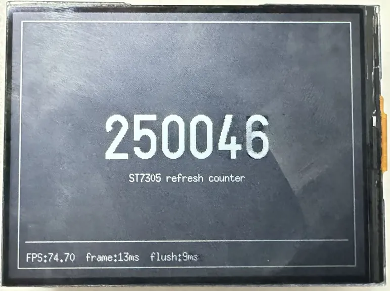 tip
tip- FPS can reach 74 frames, suitable for fast-refresh applications.