ESP32-S3-Touch-LCD-1.85C
Please note: The ESP32-S3-Touch-LCD-1.85C V1 version has been discontinued and will be replaced by the V2 version starting from January 30, 2026.
- ESP32-S3-Touch-LCD-1.85C (Standard Version)
- ESP32-S3-Touch-LCD-1.85C-BOX (With speaker box and 3.7V Lithium battery)


The ESP32-S3-Touch-LCD-1.85C (Standard Version) and ESP32-S3-Touch-LCD-1.85C-BOX (With speaker box without battery) are microcontroller development boards supporting 2.4GHz Wi-Fi and Bluetooth BLE 5. They integrate large-capacity Flash and PSRAM, feature an onboard 1.85inch circular touchscreen, and can smoothly run GUI applications such as LVGL. Combined with various peripheral interfaces, they enable rapid development of HMI and other applications based on the ESP32-S3.
| SKU | Product |
|---|---|
| 30683 | ESP32-S3-Touch-LCD-1.85C |
| 30684 | ESP32-S3-Touch-LCD-1.85C-BOX |
| 30685 | ESP32-S3-Touch-LCD-1.85C-BOX-EN |
Features
- Powered by a high-performance Xtensa 32-bit LX7 dual-core processor, with a main frequency of up to 240 MHz
- Supports 2.4 GHz Wi-Fi (802.11 b/g/n) and Bluetooth 5 (LE), with an onboard antenna
- Built-in 512KB SRAM and 384KB ROM, 16MB Flash, and 8MB PSRAM
- Onboard 1.85inch LCD screen, 360×360 resolution, 262K colors
- Supports I2C interface for touch control, with interrupt support
- Exposes UART, I2C, and some I/O interfaces
- Onboard resources include an audio codec chip, MIC, RTC clock sensor, TF card slot, and battery charging management module
- Supports flexible clock control and various power modes for low-power scenarios
Version Description
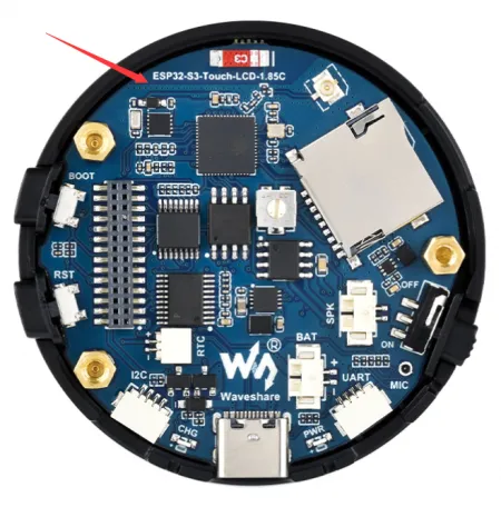
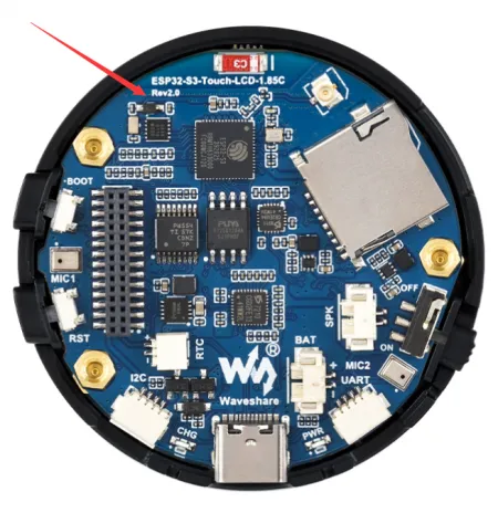
Version Identification
-
Identify via the factory firmware (the V2 version displays a Rev2.0 identifier)


-
Identify via PCB silkscreen (the V2 version has Rev2.0 silkscreen)
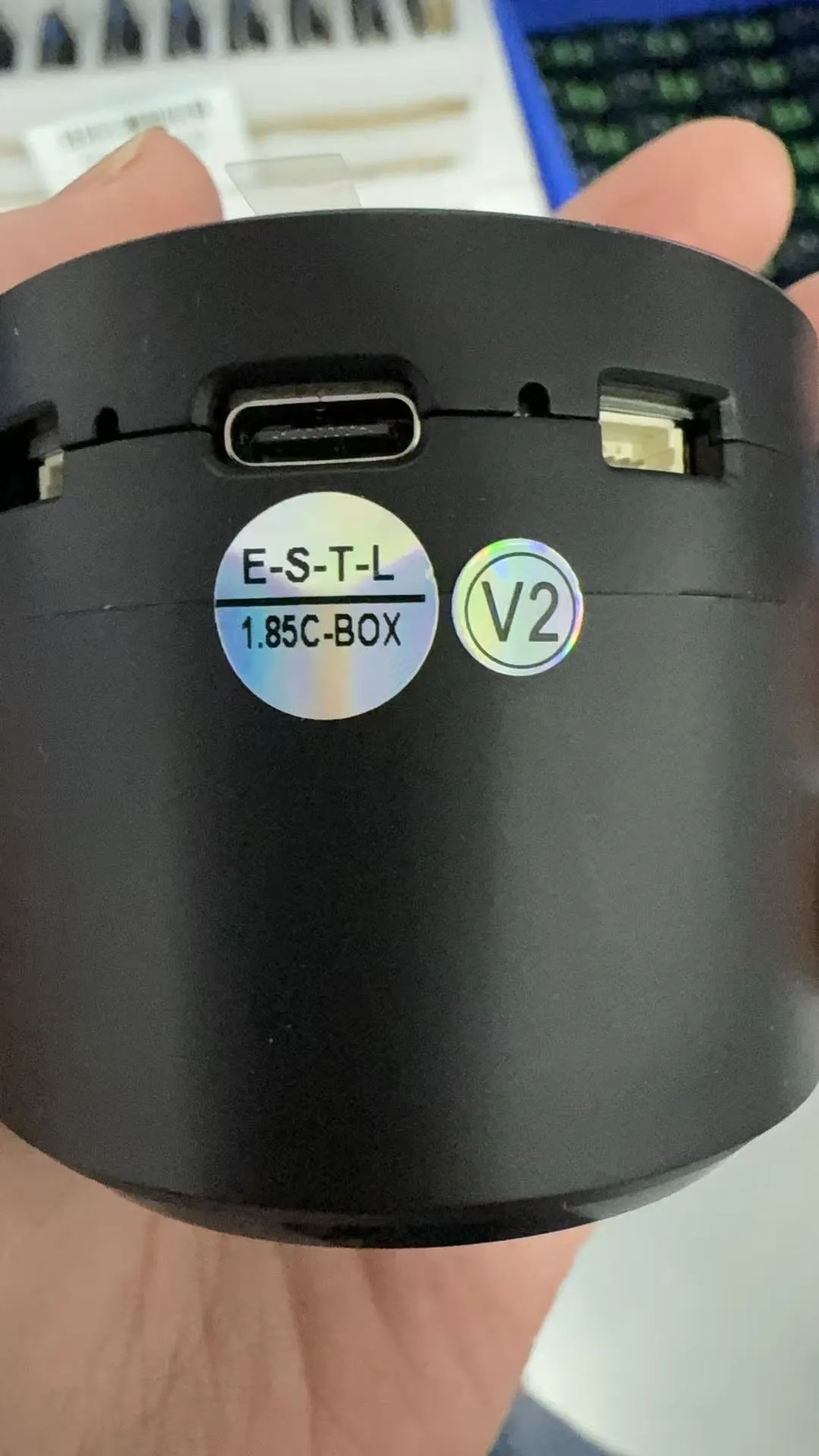
-
QC sticker on the case (the V2 version has a V2 sticker)
Hardware Differences
| Component | V1 | V2 |
|---|---|---|
| Audio Decoder | PCM5101APWR | ES8311 |
| Power Amplifier | NS8002 | NS4150B |
| Audio Encoder | None | ES7210 |
| Microphone | MEMS Digital Microphone | Analog Microphone |
| Differences | No echo cancellation, mono recording | Dual microphones with echo cancellation circuit, playback interrupt support, stereo recording, better sound pickup |
Pin Differences
| GPIO | V1 | V2 |
|---|---|---|
| GPIO2 | MIC_WS | I2S_MCLK |
| GPIO10 | NC (No function) | SCL (I2C clock line) |
| GPIO11 | NC (No function) | SDA (I2C data line) |
| GPIO15 | MIC_SCK | PA_CTRL (Amplifier control) |
| GPIO38 | I2S_LRCK | I2S_LRCK |
| GPIO39 | MIC_SD | MIC_SD |
| GPIO47 | I2S_DIN | I2S_DIN |
| GPIO48 | I2S_BCK | I2S_BCK |
Onboard Resources
Version V1.0

- ESP32-S3R8 Dual-core processor, operating frequency up to 240MHz
- 16MB Flash
- TCA9554PWR GPIO expander chip
- RTC Chip PCF85063 RTC clock
- Amplifier Chip
- PCM5101 Audio Decoder Chip
- Battery Charging Management Chip
- MP1605GTF-Z Power module, supporting up to 3.3V 2A output
- Volume Adjustment Knob
- TF Card Slot
- IPEX1 Connector Switching to use the external antenna via resoldering an onboard resistor
- Onboard Ceramic Antenna
- Battery Switch
- Speaker Header Comes with a 4 Ω 5W speaker (With speaker box version only)
- Microphone
- Battery Header MX1.25 2PIN connector for 3.7V lithium battery, supports charging and discharging
- UART Header
- Power Indicator
- USB Type-C Port
- Charging Indicator When a system battery is connected, it stays on while charging and turns off when fully charged (status indeterminate when no system battery is connected)
- I2C Header Connected to other onboard chips; only for connecting external I2C devices, cannot be remapped to other functions
- RTC Battery Header For connecting a rechargeable RTC battery
- 1.27mm Pin Header Reserved 28pin header interface, exposing GPIO and other functional pins
- RESET Button
- BOOT Button
Version V2.0
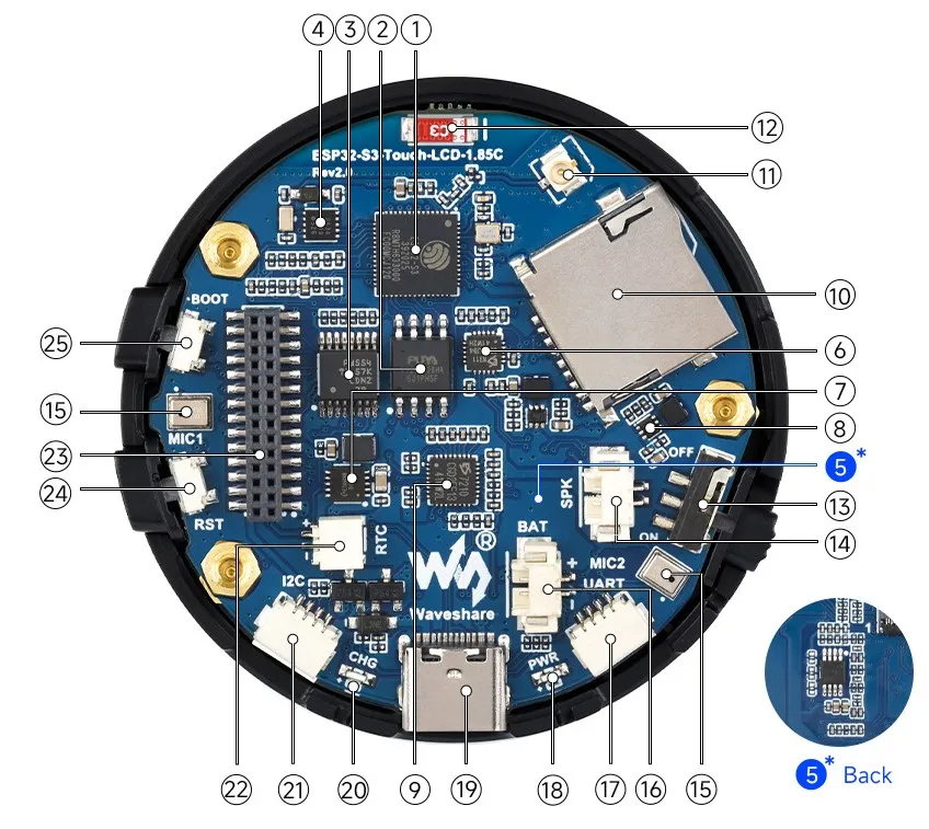
- ESP32-S3R8 Dual-core processor, operating frequency up to 240MHz
- 16MB Flash
- TCA9554PWR GPIO expander chip
- RTC Chip PCF85063 RTC clock
- Amplifier Chip
- ES8311 Audio decoder chip
- Battery Charging Management Chip
- MP1605GTF-Z Power module, supporting up to 3.3V 2A output
- ES7210 Audio encoder chip
- TF Card Slot
- IPEX1 Connector Switching to use the external antenna via resoldering an onboard resistor
- Onboard Ceramic Antenna
- Battery Switch
- Speaker Header Comes with a 4 Ω 5W speaker (With speaker box version only)
- Dual Microphones
- Battery Header MX1.25 2PIN connector for 3.7V lithium battery, supports charging and discharging
- UART Header
- Power Indicator
- USB Type-C Port
- Charging Indicator When a system battery is connected, it stays on while charging and turns off when fully charged (status indeterminate when no system battery is connected)
- I2C Header Connected to other onboard chips; only for connecting external I2C devices, cannot be remapped to other functions
- RTC Battery Header For connecting a rechargeable RTC battery
- 1.27mm Pin Header Reserved 28pin header interface, exposing GPIO and other functional pins
- RESET Button
- BOOT Button
Interface Introduction
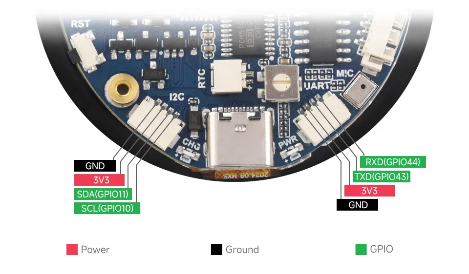
- I2C Interfaces
Pin Marking Function Description GND GND Power ground 3V3 3V3 3.3V output SCL SCL (GPIO10) I2C clock line, cannot be used as a regular GPIO SDA SDA (GPIO11) I2C data line, cannot be used as a regular GPIO - UART Interfaces
Pin Marking Function Description GND GND Power ground 3V3 3V3 3.3V output TXD TXD (GPIO43) UART data transmit or can be used as a regular GPIO RXD RXD (GPIO44) UART data receive or can be used as a regular GPIO - USB Interfaces
Pin Marking Function Description 5V 5V 5V output GND GND Power ground DN DN (GPIO19) Used for USB communication or as a regular GPIO. If used as a regular GPIO, you must enter download mode before each program flash DP DP (GPIO20) Used for USB communication or as a regular GPIO. If used as a regular GPIO, you must enter download mode before each program flash
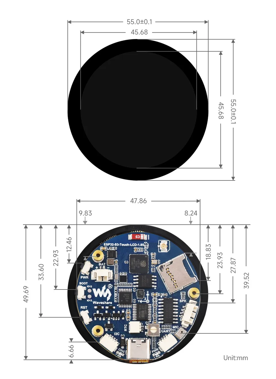
Dimensions
Development Methods
The ESP32-S3-Touch-LCD-1.85 supports two development frameworks: Arduino IDE and ESP-IDF, providing flexibility for developers to choose the tool that best fits their project requirements and personal preference.
Both development methods have their own advantages. Developers can choose based on their needs and skill levels. Arduino is simple to learn and quick to start, suitable for beginners and non-professionals. ESP-IDF provides more advanced development tools and stronger control capabilities, suitable for developers with professional backgrounds or higher performance requirements, and is more appropriate for complex project development.
-
Arduino IDE is a convenient, flexible, and easy-to-use open-source electronics prototyping platform. It requires minimal foundational knowledge, allowing for rapid development after a short learning period. Arduino has a huge global user community, providing a vast amount of open-source code, project examples, and tutorials, as well as a rich library ecosystem that encapsulates complex functions, enabling developers to implement various features rapidly. You can refer to the Working with Arduino to complete the initial setup, and the tutorial also provides related demos for reference.
-
ESP-IDF, short for Espressif IoT Development Framework, is a professional development framework launched by Espressif Systems for its ESP series of chips. It is based on C language development and includes compilers, debuggers, flashing tools, etc. It supports development via command line or integrated development environments (such as Visual Studio Code with the Espressif IDF plugin), which provides features like code navigation, project management, and debugging. We recommend using VS Code for development. For the specific configuration process, please refer to the Working with ESP-IDF. The tutorial also provides relevant demos for reference.