Working with Arduino
This chapter contains the following sections. Please read as needed:
Arduino Getting Started
New to Arduino ESP32 development and looking for a quick start? We have prepared a comprehensive Getting Started Tutorial for you.
- Section 0: Getting to Know ESP32
- Section 1: Installing and Configuring Arduino IDE
- Section 2: Arduino Basics
- Section 3: Digital Output/Input
- Section 4: Analog Input
- Section 5: Pulse Width Modulation (PWM)
- Section 6: Serial Communication (UART)
- Section 7: I2C Communication
- Section 8: SPI Communication
- Section 9: Wi-Fi Basics
- Section 10: Web Server
- Section 11: Bluetooth
- Section 12: LVGL GUI Development
- Section 13: Comprehensive Project
Note: This tutorial uses the ESP32-S3-Zero as a reference example, and all hardware code is based on its pinout. Before you start, we recommend checking the pinout of your development board to ensure the pin configuration is correct.
Setting Up Development Environment
1. Installing and Configuring Arduino IDE
For the ESP32-S3-ePaper-1.54 development board, the Arduino IDE requires the installation of arduino-esp32 v3.3.0 or higher.
Please refer to the tutorial Installing and Configuring Arduino IDE to download and install the Arduino IDE and add ESP32 support.
2. Installing Libraries
- When installing Arduino libraries, there are typically two methods: Install Online and Install Offline. If the library installation requires Install Offline, you must use the provided library file.
- For most libraries, users can easily search for and install them via the Arduino IDE's online Library Manager. However, some open-source or custom libraries are not synchronized to the Arduino Library Manager and therefore cannot be found through online search. In this case, users can only install these libraries manually via offline methods.
- The sample program package for the ESP32-S3-ePaper-1.54 development board can be downloaded from here. The
Arduino\librariesdirectory within the package already contains all the library files required for this tutorial.
| Library/File Name | Description | Version | Installation Method |
|---|---|---|---|
| LVGL | Graphical library | v8.3.11/v9.3.0 | "Install Offline" |
| SensorLib | Sensor control library | v0.3.1 | "Install Online" or "Install Offline" |
There are strong dependencies between versions of LVGL and its driver libraries. For example, a driver written for LVGL v8 may not be compatible with LVGL v9. To ensure that the examples can be reproduced reliably, it is recommended to use the specific versions listed in the table above. Mixing different versions of libraries may lead to compilation failures or runtime errors.
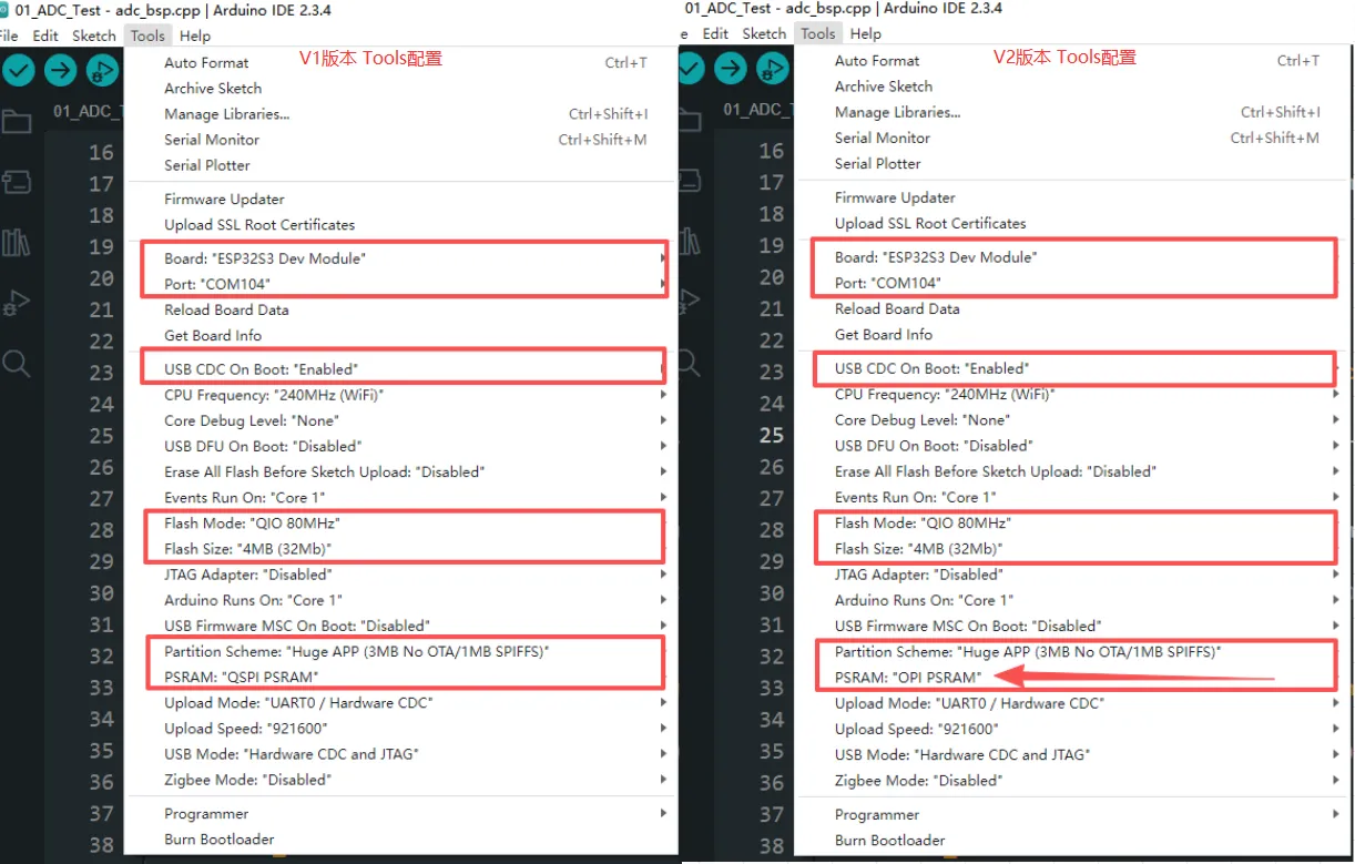
3. Arduino Project Parameter Settings
Demo
The Arduino demos are located in the Arduino/examples directory of the demo package.
| Demo | Basic Program Description | Dependency Library |
|---|---|---|
| 01_ADC_Test | Get the voltage value of the lithium battery | - |
| 02_I2C_PCF85063 | Print real-time time of RTC chip | SensorLib |
| 03_I2C_STHC3 | Get data from SHTC3 temperature & humidity sensor | - |
| 04_SD_Card | Load and display TF card information | - |
| 05_WIFI_AP | Set to AP mode to obtain the IP address of the access device | - |
| 06_WIFI_STA | Set to STA mode to connect to Wi-Fi and obtain an IP address | - |
| 07_BATT_PWR_Test | Control power via the PWR button when powered solely by the lithium battery | - |
| 08_Audio_Test | Play the sound recorded by the microphone through the speaker | - |
| 09_LVGL_V8_Test | LVGLV8 demo | LVGL V8.3.11 |
| 10_LVGL_V9_Test | LVGLV9 demo | LVGL V9.3.0 |
| 11_RTC_Sleep_Test | Implements RTC wake-up in low-power mode | LVGL V8.3.11 |
| 12_FT6336_Test | Drive the FT6336 touch controller | - |
01_ADC_Test
Demo Description
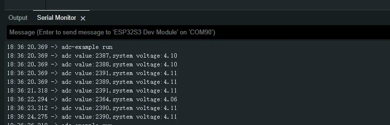
- The analog voltage connected through the GPIO is converted to digital by the ADC, and then the actual lithium battery voltage is calculated and printed to the terminal.
Hardware Connection
- Connect the board to the computer using a USB cable
Code Analysis
adc_bsp_init(void): Initializes ADC1, including creating an ADC one-shot trigger unit and configuring Channel 3 of ADC1.adc_get_value(float *value,int *data): Reads the value from Channel 3 of ADC1, calculates the corresponding voltage based on the reference voltage and resolution, and stores it at the location pointed to by the passed pointer. Stores 0 if the read fails.adc_example(void* parameter): After initializing ADC1, creates an ADC task. This task reads the ADC value every second and calculates the system voltage from the raw ADC reading.
Operation Result
-
After the program is compiled and downloaded, you can view the printed ADC values and voltage output by opening the Serial Monitor, as shown in the following image:
02_I2C_PCF85063
Demo Description
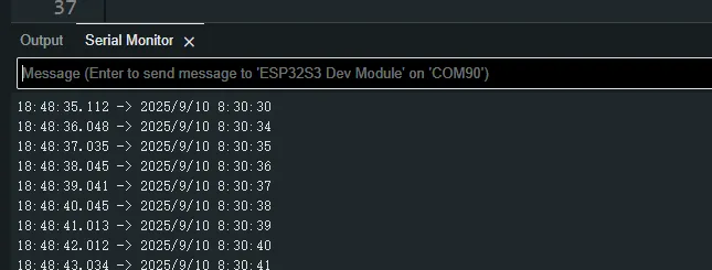
- Through the I2C protocol, initialize the PCF85063 chip, set the time, and then periodically read the time and print it to the terminal
Hardware Connection
- Connect the board to the computer using a USB cable
Code Analysis
void i2c_rtc_loop_task(void *arg): Creates an RTC task to implement the RTC function, reading the clock of the RTC chip every second and outputting it to the terminal.
Operation Result
-
After the program is compiled and downloaded, open the serial port monitoring to see the RTC time of the printout, as shown in the following figure:
03_I2C_STHC3
Demo Description
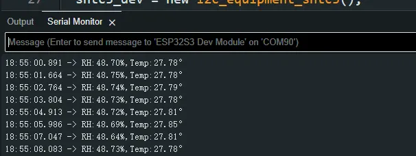
- Initialize the SHTC3 chip through the I2C protocol, and then print the temperature and humidity information read every 1 second to the terminal
Hardware Connection
- Connect the board to the computer using a USB cable
Code Analysis
void i2c_SHTC3_loop_task(void *arg): Creates a task for the SHTC3 sensor to periodically obtain temperature and humidity data.
Operation Result
-
Open the serial port monitor, you can see the printed temperature and humidity data, as shown in the figure below:
04_SD_Card
Demo Description
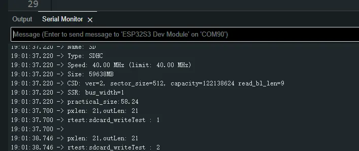
- Drive the TF card through SDMMC, and print the TF card information to the terminal after successfully mounting.
Hardware Connection
- Install a FatFs-formatted into the board before powering on
Code Analysis
-
sdcard_init(void): Initializes the TF card using 1-line SDMMC mode. -
sdcard_loop_task(void *arg): A task to test TF card read/write functionality. You need to uncomment the#define sdcard_write_Testmacro definition.//#define sdcard_write_Test
Operation Result
-
Click on the serial port monitoring device, you can see the output information of the TF card, as shown in the figure below:
05_WIFI_AP
Demo Description
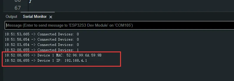
- This demo can set the development board as a hotspot, allowing phones or other devices in STA mode to connect to the development board.
Hardware Connection
- Connect the board to the computer using a USB cable
Code Analysis
-
In the
05_WIFI_AP.inofile, locatessidandpassword. Phones or other STA mode devices can then connect to the board using this SSID and password.const char *ssid = "ESP32_AP";const char *password = "12345678";
Operation Result
-
After flashing the program, open the Serial Terminal. If a device successfully connects to the hotspot, the MAC address of that device will be output, as shown:
06_WIFI_STA
Demo Description
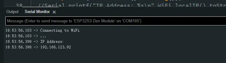
- This example configures the development board as a STA device to connect to a router, thereby accessing the system network.
Hardware Connection
- Connect the board to the computer using a USB cable
Code Analysis
-
In the
06_WIFI_STA.inofile, locatessidandpassword, and modify them to match the SSID and Password of an available router in your current environment.const char *ssid = "you_ssid";const char *password = "you_password";
Operation Result
-
After flashing the program, open the Serial Terminal. If the device successfully connects to the hotspot, the obtained IP address will be output, as shown in the figure:
07_BATT_PWR_Test
Demo Description
- Demonstrates how to control the system power via the PWR button when powered by the lithium battery.
Hardware Connection
- Connect the board to the computer using a USB cable
Code Analysis
setup_ui(lv_ui *ui): Initializes the UI interface for visual control.user_button_init(): Initializes the buttons and their trigger events.example_button_pwr_task(void* parmeter): Task that waits for button event triggers.
Operation Result
-
After the program is flashed, disconnect the USB power supply and connect the lithium battery. Power on by pressing and holding the PWR button, as shown in the figure:
 tip
tip- Press and hold the PWR button, wait for the screen to display "On", which means that the startup is successful, and release the button
- Press and hold the PWR button again, wait for the screen to display "Off", which means that the power is turned off successfully, and release the button
08_Audio_Test
Demo Description
- Demonstrates how to get data from the microphone and then play it through the speaker
Hardware Connection
- Connect the board to the computer using a USB cable
Code Analysis
i2c_master_Init(): Initializes the I2C bus.user_ui_init(): Initializes the global UI.user_button_init(): Initializes the audio interface.
Operation Result
-
After the program is flashed, as shown in the figure:
 tip
tip- Double-click the BOOT button to enter recording mode, speak into the MIC, and it will automatically end after 3 seconds
- Click the BOOT button to play the sound you just recorded (there will be a harsh noise when playing without recording data)
09_LVGL_V8_Test
Demo Description
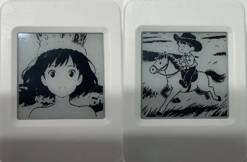
- Helps users quickly implement UI design by porting LVGL V8.
Hardware Connection
- Connect the board to the computer using a USB cable
Code Analysis
void loop_lvgl_img(void *arg): Creates an image component task that switches pictures every 5 seconds.void led_test_task(void *arg): LED blinking task.
Operation Result
-
After the program is flashed, the device operation result is as follows:
10_LVGL_V9_Test
Demo Description
- Helps users quickly implement UI design by porting LVGL V9.
Hardware Connection
- Connect the board to the computer using a USB cable
Code Analysis
void loop_lvgl_img(void *arg): Creates an image component task that switches pictures every 5 seconds.void led_test_task(void *arg): LED blinking task.
Operation Result
-
After the program is flashed, the device operation result is as follows:

11_RTC_Sleep_Test
Demo Description
- Implements RTC wake-up in low-power mode.
Hardware Connection
- Connect the board to the computer using a USB cable
Code Analysis
void set_rtcAlarmSec(int sec): Sets the RTC alarm for a specific second (absolute time).void set_rtcAlarmMinute(int min): Sets the RTC alarm for a specific minute (absolute time).void set_rtcAlarmHour(int hour): Sets the RTC alarm for a specific hour (absolute time).void set_rtcAlarmDay(int day): Sets the RTC alarm for a specific day (absolute time).
Operation Result
-
After the program is flashed, the device operation result is as follows:
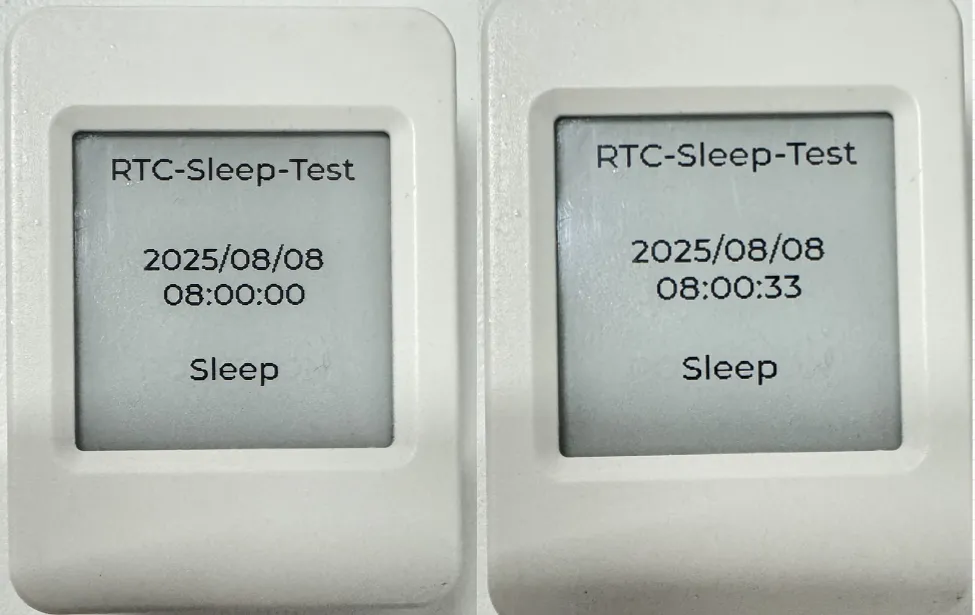 tip
tip- The initial RTC time is set to: 2025/08/08 08:00:00. The second alarm is set to 30 seconds (this is absolute time, e.g., 08:00:30, 08:01:30, 08:02:30).
- After waking up, it reads the RTC value, enters low-power mode, and waits for the RTC alarm to trigger the next wake-up.
- In low-power mode, a single click of the PWR button can power off the system. Pressing and holding the BOOT button can reset the RTC time to 2025/08/08 08:00:00.
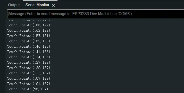
12_FT6336_Test
Demo Description
- Drives the FT6336 touch controller via the I2C bus, obtains touch coordinates, and prints them to the terminal.
Hardware Connection
- Connect the board to the computer using a USB cable
Code Analysis
i2c_bus = I2cMasterBus::requestInstance(ESP32_I2C_SCL_PIN, ESP32_I2C_SDA_PIN, ESP32_I2C_DEV_NUM); // Obtain I2C bus control handle
assert(i2c_bus);
ft6336_dev = I2cFt6336Dev::requestInstance(i2c_bus->Get_I2cBusHandl(),I2C_FT6336_DEV_Address,EPD_WIDTH,EPD_HEIGHT); // Obtain touch controller control handle
assert(ft6336_dev);
ft6336_dev->GetTouchPoint(&x,&y); // Get touch coordinates
Operation Result
-
After the program is uploaded, touch the screen and the terminal will print the corresponding coordinate values, as shown below:
 tip
tip- This example is only available for the touch-enabled version.
- The V1 version series does not include a touch-enabled version.