ESP-IDF
This chapter contains the following sections. Please read as needed:
ESP-IDF Getting Started
New to ESP32 ESP-IDF development and looking to get started quickly? We have prepared a general Getting Started Tutorial for you.
- Section 1: Environment Setup
- Section 2: Running Examples
- Section 3: Creating a Project
- Section 4: Using Components
- Section 5: Debugging
- Section 6: FreeRTOS
- Section 7: Peripherals
- Section 8: Wi-Fi Programming
- Section 9: BLE Programming
Please Note: This tutorial uses the ESP32-S3-Zero as a teaching example, and all hardware code is based on its pinout. Before you start, it is recommended that you check the pinout of your development board to ensure the pin configuration is correct.
Setting Up Development Environment
For the ESP32-S3-ePaper-1.54 development board, ESP-IDF version V5.5.0 or above is required.
The following guide uses Windows as an example, demonstrating development using VS Code + the ESP-IDF extension. macOS and Linux users should refer to the official documentation.
The screenshots in this section use ESP-IDF V5.5.2 as an example. When installing, please select the ESP-IDF version that matches your board's example.
Install the ESP-IDF Development Environment
-
Download the installation manager from the ESP-IDF Installation Manager page. This is Espressif's latest cross-platform installer. The following steps demonstrate how to use its offline installation feature.
Click the Offline Installer tab on the page, then select Windows as the operating system and the ESP-IDF version you need (the version shown in the screenshot is for reference only — choose the version that fits your actual needs).

After confirming your selection, click the download button. The browser will automatically download two files: the ESP-IDF Offline Package (.zst) and the ESP-IDF Installer (.exe).

Please wait for both files to finish downloading.
-
Once the download is complete, double-click to run the ESP-IDF Installer (eim-gui-windows-x64.exe).
The installer will automatically detect if the offline package exists in the same directory. Click Install from archive.

Next, select the installation path. We recommend using the default path. If you need to customize it, ensure the path does not contain Chinese characters or spaces. Click Start installation to proceed.

-
When you see the following screen, the ESP-IDF installation is successful.

-
We recommend installing the drivers as well. Click Finish installation, then select Install driver.

Install Visual Studio Code and the ESP-IDF Extension
-
Download and install Visual Studio Code.
-
During installation, it is recommended to check Add "Open with Code" action to Windows Explorer file context menu to facilitate opening project folders quickly.
-
In VS Code, click the Extensions icon
 in the Activity Bar on the side (or use the shortcut Ctrl + Shift + X) to open the Extensions view.
 -
Enter ESP-IDF in the search box, locate the ESP-IDF extension, and click Install.

-
For ESP-IDF extension versions ≥ 2.0, the extension will automatically detect and recognize the ESP-IDF environment installed in the previous steps, requiring no manual configuration.
Demo
The ESP-IDF demos are located in the ESP-IDF directory of the demo package.
| Demo | Basic Program Description | Dependency Library |
|---|---|---|
| 01_ADC_Test | Get the voltage value of the lithium battery | - |
| 02_I2C_PCF85063 | Print real-time time of RTC chip | SensorLib |
| 03_I2C_STHC3 | Get data from SHTC3 temperature & humidity sensor | - |
| 04_SD_Card | Load and display TF card information | - |
| 05_WIFI_AP | Set to AP mode to obtain the IP address of the access device | - |
| 06_WIFI_STA | Set to STA mode to connect to Wi-Fi and obtain an IP address | - |
| 07_BATT_PWR_Test | Control power via the PWR button when powered solely by the lithium battery | - |
| 08_Audio_Test | Play the sound recorded by the microphone through the speaker | LVGL V8.3.11 |
| 09_LVGL_V8_Test | LVGLV8 demo | LVGL V8.3.11 |
| 10_LVGL_V9_Test | LVGLV9 demo | LVGL V9.3.0 |
| 11_FactoryProgram | Comprehensive demo | LVGL V8.3.11 |
| 12_RTC_Sleep_Test | Implements RTC wake-up in low-power mode | LVGL V8.3.11 |
| 13_FT6336_Test | Drive the FT6336 touch controller | - |
01_ADC_Test
Demo Description
- The analog voltage connected through the GPIO is converted to digital by the ADC, and then the actual lithium battery voltage is calculated and printed to the terminal.
Hardware Connection
- Connect the board to the computer using a USB cable
Code Analysis
Adc_PortInit(void): Initializes ADC1, including creating an ADC one-time trigger unit and configuring channel 3 for ADC1float Adc_GetBatteryVoltage(int *data): Reads the value from ADC1 channel 3 and returns the actual voltage value.uint8_t Adc_GetBatteryLevel(void): Returns the battery percentage.void Adc_LoopTask(void *arg): Creates an ADC task that reads the ADC value and prints it to the serial port every second.
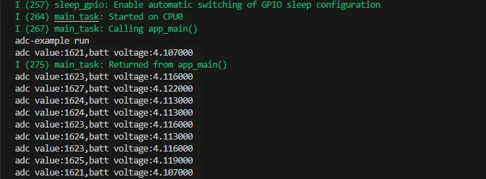
Operation Result
-
After the program is compiled and downloaded, you can view the printed ADC values and voltage output by opening the Serial Monitor, as shown in the following image:
02_I2C_PCF85063
Demo Description
- Through the I2C protocol, initialize the PCF85063 chip, set the time, and then periodically read the time and print it to the terminal
Hardware Connection
- Connect the board to the computer using a USB cable
Code Analysis
void i2c_rtc_loop_task(void *arg): Creates an RTC task to implement the RTC function, reading the clock of the RTC chip every second and outputting it to the terminal.
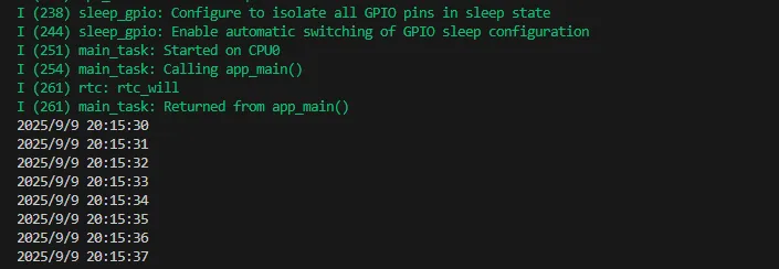
Operation Result
-
After the program is compiled and downloaded, open the serial port monitoring to see the RTC time of the printout, as shown in the following figure:
03_I2C_STHC3
Demo Description
- Uses the I2C protocol to initialize and configure the SHTC3 chip, then reads and prints temperature and humidity information to the terminal every second.
Hardware Connection
- Connect the board to the computer using a USB cable
Code Analysis
void i2c_SHTC3_loop_task(void *arg): Creates a task for the SHTC3 sensor to periodically obtain temperature and humidity data.
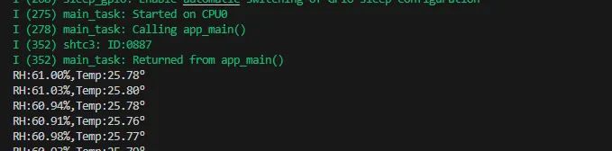
Operation Result
-
Open the serial port monitor, you can see the printed temperature and humidity data, as shown in the figure below:
04_SD_Card
Demo Description
- Drive the TF card through SDMMC, and print the TF card information to the terminal after successfully mounting.
Hardware Connection
- Install a FatFs-formatted into the board before powering on
Code Analysis
sdcard_init(void): Initializes the TF card using 1-line SDMMC mode.sdcard_loop_task(void *arg): A task to test TF card read/write functionality. You need to uncomment the#define sdcard_write_Testmacro definition.
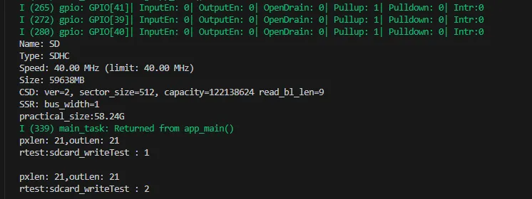
Operation Result
-
Click to open the Serial Monitor device. You can see the output TF card information; practical_size indicates the actual capacity of the TF card, as shown below:
05_WIFI_AP
Demo Description
- This demo can set the development board as a hotspot, allowing phones or other devices in STA mode to connect to the development board.
Hardware Connection
- Connect the board to the computer using a USB cable
Code Analysis
-
In the
05_WIFI_AP.inofile, locate thessidandpassword. Phones or other STA mode devices can then connect to the development board using this SSID and password.#define EXAMPLE_ESP_WIFI_SSID "waveshare_esp32"#define EXAMPLE_ESP_WIFI_PASSWORD "wav123456"
Operation Result
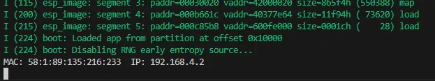
-
After flashing the program, open the serial terminal, if the device is successfully connected to the hotspot, the MAC address and IP address of the device will be output, as shown in the figure:
06_WIFI_STA
Demo Description
- This example configures the development board as a STA device to connect to a router, thereby accessing the system network.
Hardware Connection
- Connect the board to the computer using a USB cable
Code Analysis
-
In the file
esp_wifi_bsp.c, findssidandpassword, then modify them to the SSID and Password of an available router in your current environment.wifi_config_t wifi_config = {.sta = {.ssid = "PDCN",.password = "1234567890",},};
Operation Result
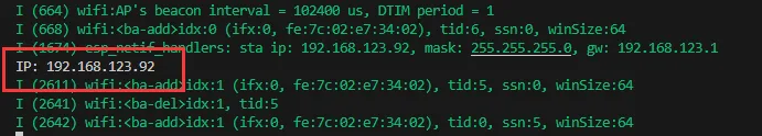
-
After flashing the program, open the Serial Terminal. If the device successfully connects to the hotspot, the obtained IP address will be output, as shown in the figure:
07_BATT_PWR_Test
Demo Description
- Demonstrates how to control the system power via the PWR button when powered by the lithium battery.
Hardware Connection
- Connect the board to the computer using a USB cable
Code Analysis
setup_ui(lv_ui *ui): Initializes the UI interface for visual control.user_button_init(): Initializes the buttons and their trigger events.example_button_pwr_task(void* parmeter): Task that waits for button event triggers.
Operation Result
-
After the program is flashed, disconnect the USB power supply and connect the lithium battery. Power on by pressing and holding the PWR button, as shown in the figure:
 tip
tip- Press and hold the PWR button. Wait for the screen to display "ON", indicating successful startup, then release the button.
- Press and hold the PWR button again. Wait for the screen to display "OFF", indicating successful power shutdown, then release the button.
08_Audio_Test
Demo Description
- Demonstrates how to get data from the microphone and then play it through the speaker
Hardware Connection
- Connect the board to the computer using a USB cable
Code Analysis
i2c_master_Init(): Initializes the I2C bus.user_ui_init(): Initializes the global UI.user_button_init(): Initializes the audio interface.
Operation Result
-
After the program is flashed, as shown in the figure:
 tip
tip- Double-click the BOOT button to enter recording mode, speak into the MIC, and it will automatically end after 3 seconds
- Click the BOOT button to play the sound you just recorded
- Double-click the PWR button to play a piece of music
- Click the PWR button to interrupt music playback
09_LVGL_V8_Test
Demo Description
- Helps users quickly implement UI design by porting LVGL V8.
Hardware Connection
- Connect the board to the computer using a USB cable
Code Analysis
void loop_lvgl_img(void *arg): Creates an image component task that switches pictures every 5 seconds.void led_test_task(void *arg): LED blinking task.
Operation Result
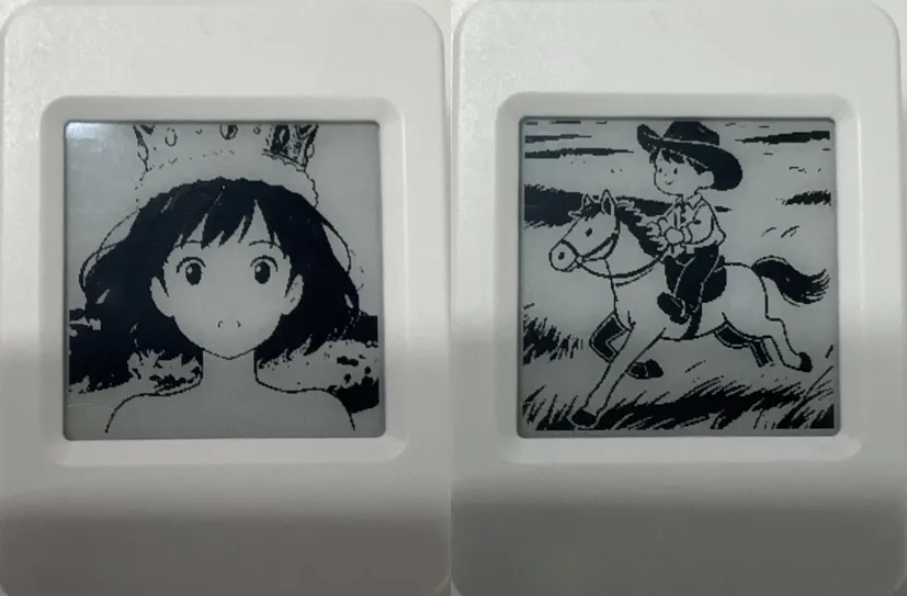
-
After the program is flashed, the device operation result is as follows:
10_LVGL_V9_Test
Demo Description
- Helps users quickly implement UI design by porting LVGL V9.
Hardware Connection
- Connect the board to the computer using a USB cable
Code Analysis
void loop_lvgl_img(void *arg): Creates an image component task that switches pictures every 5 seconds.void led_test_task(void *arg): LED blinking task.
Operation Result
-
After the program is flashed, the device operation result is as follows:

11_FactoryProgram
Demo Description
- Comprehensive project, you can simply test the onboard hardware functions, or directly use the BIN firmware we provide for flashing.
Hardware Connection
- Connect the board to the computer using a USB cable
Code Analysis
BoardPower_Init(); // Power initialization
BoardPower_EPD_ON();     // Turn on e-Paper power
BoardPower_Audio_ON();   // Turn on audio power
BoardPower_VBAT_ON();    // Enable BAT power
FacTestEventGroup = xEventGroupCreate();
i2c_bus = I2cMasterBus::requestInstance(ESP32_I2C_SCL_PIN,ESP32_I2C_SDA_PIN,ESP32_I2C_DEV_NUM); // Initialize I2C
assert(i2c_bus);
ft6336_dev = I2cFt6336Dev::requestInstance(i2c_bus->Get_I2cBusHandle(),I2C_FT6336_DEV_Address,EPD_WIDTH,EPD_HEIGHT); // Initialize touch
assert(ft6336_dev);
ft6336_dev->Ft6336_Reset(EPD_TP_RST_PIN);

esp_err_t ret = pcf85063a_init(&pcf85063, i2c_bus->Get_I2cBusHandle(), PCF85063A_ADDRESS); // Initialize RTC
if (ret != ESP_OK) {
  ESP_LOGE(TAG, "Failed to initialize PCF85063A (error: %d)", ret);
  pcf85063initflag = 0;
}
boot_button = new Button(BOOT_BUTTON_PIN);
power_button = new Button(PWR_BUTTON_PIN);
while(0 == gpio_get_level(PWR_BUTTON_PIN)) { // Wait for the power button to be released
  vTaskDelay(pdMS_TO_TICKS(100));
}
InitializeButtons();                         // Initialize buttons
sdcardinitflag = Sdcard_Init();             // Initialize TF card
BoardAdc_Init();
Shtc3_Init(i2c_bus);
Touch_ISR_GPIO_Init();
Codec_StartInit();
Operation Result
-
After the program is flashed, the device operation result is as follows:
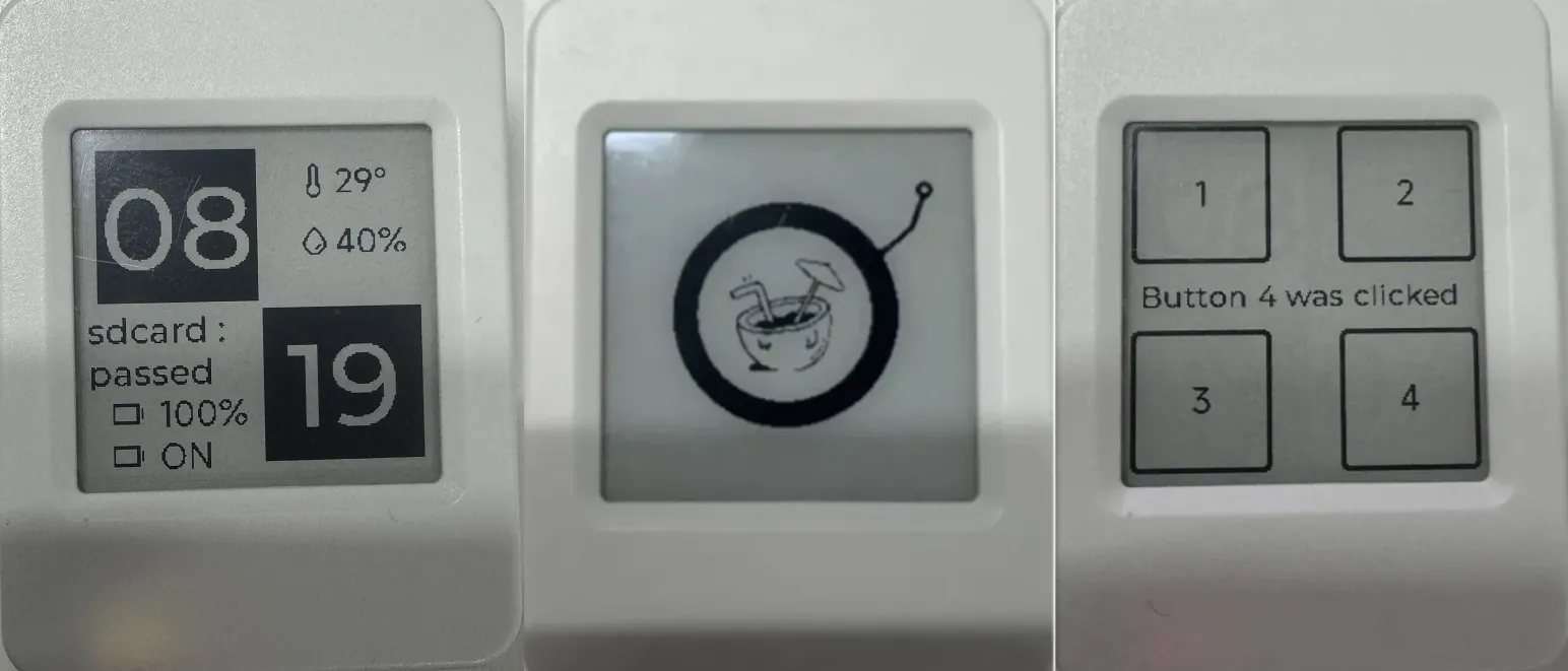 tip
tip- Use the main interface to determine whether the onboard hardware is functioning properly.
- Click the PWR button to navigate to the music interface. Refer to the source code for related settings.
- Double-press the PWR button to jump to the touch interface, where you can quickly test touch functionality (touch version only).
12_RTC_Sleep_Test
Demo Description
- Implements RTC wake-up in low-power mode.
Hardware Connection
- Connect the board to the computer using a USB cable
Code Analysis
void set_rtcAlarmSec(int sec): Sets the RTC alarm for a specific second (absolute time).void set_rtcAlarmMinute(int min): Sets the RTC alarm for a specific minute (absolute time).void set_rtcAlarmHour(int hour): Sets the RTC alarm for a specific hour (absolute time).void set_rtcAlarmDay(int day): Sets the RTC alarm for a specific day (absolute time).
Operation Result
-
After the program is flashed, the device operation result is as follows:
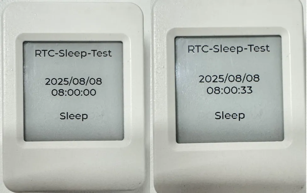 tip
tip- The initial RTC time is set to: 2025/08/08 08:00:00. The second alarm is set to 30 seconds (this is absolute time, e.g., 08:00:30, 08:01:30, 08:02:30).
- After waking up, it reads the RTC value, enters low-power mode, and waits for the RTC alarm to trigger the next wake-up.
- In low-power mode, a single click of the PWR button can power off the system. Pressing and holding the BOOT button can reset the RTC time to 2025/08/08 08:00:00.
13_FT6336_Test
Demo Description
- Drives the FT6336 touch controller via the I2C bus, obtains touch coordinates, and prints them to the terminal.
Hardware Connection
- Connect the board to the computer using a USB cable
Code Analysis
i2c_bus = I2cMasterBus::requestInstance(ESP32_I2C_SCL_PIN, ESP32_I2C_SDA_PIN, ESP32_I2C_DEV_NUM); // Obtain I2C bus control handle
assert(i2c_bus);
ft6336_dev = I2cFt6336Dev::requestInstance(i2c_bus->Get_I2cBusHandl(),I2C_FT6336_DEV_Address,EPD_WIDTH,EPD_HEIGHT); // Obtain touch controller control handle
assert(ft6336_dev);
ft6336_dev->GetTouchPoint(&x,&y); // Get touch coordinates
Operation Result
-
After the program is uploaded, touch the screen and the terminal will print the corresponding coordinate values, as shown below:
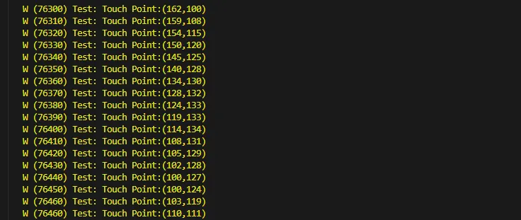 tip
tip- This example is only available for the touch-enabled version.
- The V1 version series does not include a touch-enabled version.