ESP-IDF
This chapter includes the following sections;
ESP-IDF Getting Started Tutorial
New to ESP32 ESP-IDF development and looking to get started quickly? We have prepared a general Getting Started Tutorial for you.
- Section 1: Environment Setup
- Section 2: Running Examples
- Section 3: Creating a Project
- Section 4: Using Components
- Section 5: Debugging
- Section 6: FreeRTOS
- Section 7: Peripherals
- Section 8: Wi-Fi Programming
- Section 9: BLE Programming
Please Note: This tutorial uses the ESP32-S3-Zero as a teaching example, and all hardware code is based on its pinout. Before you start, it is recommended that you check the pinout of your development board to ensure the pin configuration is correct.
Setting up the Development Environment
For the ESP32-S3-Touch-AMOLED-1.32 development board, you need to use ESP-IDF V5.5.0 or higher.
The following guide uses Windows as an example, demonstrating development using VS Code + the ESP-IDF extension. macOS and Linux users should refer to the official documentation.
The screenshots in this section use ESP-IDF V5.5.2 as an example. When installing, please select the ESP-IDF version that matches your board's example.
Install the ESP-IDF Development Environment
-
Download the installation manager from the ESP-IDF Installation Manager page. This is Espressif's latest cross-platform installer. The following steps demonstrate how to use its offline installation feature.
Click the Offline Installer tab on the page, then select Windows as the operating system and the ESP-IDF version you need (the version shown in the screenshot is for reference only — choose the version that fits your actual needs).

After confirming your selection, click the download button. The browser will automatically download two files: the ESP-IDF Offline Package (.zst) and the ESP-IDF Installer (.exe).

Please wait for both files to finish downloading.
-
Once the download is complete, double-click to run the ESP-IDF Installer (eim-gui-windows-x64.exe).
The installer will automatically detect if the offline package exists in the same directory. Click Install from archive.

Next, select the installation path. We recommend using the default path. If you need to customize it, ensure the path does not contain Chinese characters or spaces. Click Start installation to proceed.

-
When you see the following screen, the ESP-IDF installation is successful.

-
We recommend installing the drivers as well. Click Finish installation, then select Install driver.

Install Visual Studio Code and the ESP-IDF Extension
-
Download and install Visual Studio Code.
-
During installation, it is recommended to check Add "Open with Code" action to Windows Explorer file context menu to facilitate opening project folders quickly.
-
In VS Code, click the Extensions icon
 in the Activity Bar on the side (or use the shortcut Ctrl + Shift + X) to open the Extensions view.
 -
Enter ESP-IDF in the search box, locate the ESP-IDF extension, and click Install.

-
For ESP-IDF extension versions ≥ 2.0, the extension will automatically detect and recognize the ESP-IDF environment installed in the previous steps, requiring no manual configuration.
Example
The ESP-IDF demo is located in the ESP-IDF directory of the [https://github.com/waveshareteam/ESP32-C6-Touch-LCD-1.83/tree/main/examples demo] package.
| Demo | Basic Program Description | Dependency Library |
|---|---|---|
| 01_ADC_Test | Get the voltage value of the lithium battery | - |
| 02_WIFI_AP | Set to AP mode to obtain the IP address of the access device | - |
| 03_WIFI_STA | Set to STA mode to connect to WiFi and obtain an IP address | - |
| 04_BATT_PWR_Test | Control power via the PWR button when powered solely by the lithium battery | - |
| 05_Audio_Test | Play the sound recorded by the microphone through the speaker | LVGL V8.3.11 |
| 06_LVGL_V8_Test | LVGLV8 demo | LVGL V8.3.11 |
| 07_LVGL_V9_Test | LVGLV9 demo | LVGL V9.3.0 |
| 08_FactoryProgram | Comprehensive demo | LVGL V8.3.11 |
01_ADC_Test
Description
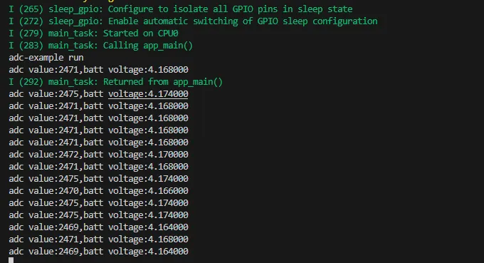
- The analog voltage connected through the GPIO is converted to digital by the ADC, and then the actual lithium battery voltage is calculated and printed to the terminal.
Hardware Connection
- Connect the board to the computer using a USB cable
Code Analysis
adc_bsp_init(void): Initializes ADC1, including creating an ADC one-shot trigger unit and configuring Channel 3 of ADC1.adc_get_value(float *value,int *data): Reads the value from Channel 3 of ADC1, calculates the corresponding voltage based on the reference voltage and resolution, and stores it at the location pointed to by the passed pointer. Stores 0 if the read fails.adc_example(void* parameter): After initializing ADC1, creates an ADC task. This task reads the ADC value every second and calculates the system voltage from the raw ADC reading.
Operation Result
-
After the program is compiled and downloaded, you can view the printed ADC values and voltage output by opening the Serial Monitor, as shown in the following image:
02_WIFI_AP
Description
- This demo can set the development board as a hotspot, allowing phones or other devices in STA mode to connect to the development board.
Hardware Connection
- Connect the board to the computer using a USB cable
Code Analysis
-
In the file
softap_example_main.c, findSSIDandPASSWORD, and then your phone or other device in STA mode can use the SSID and PASSWORD to connect to the development board.#define EXAMPLE_ESP_WIFI_SSID "waveshare_esp32"#define EXAMPLE_ESP_WIFI_PASSWORD "wav123456"
Operation Result
-
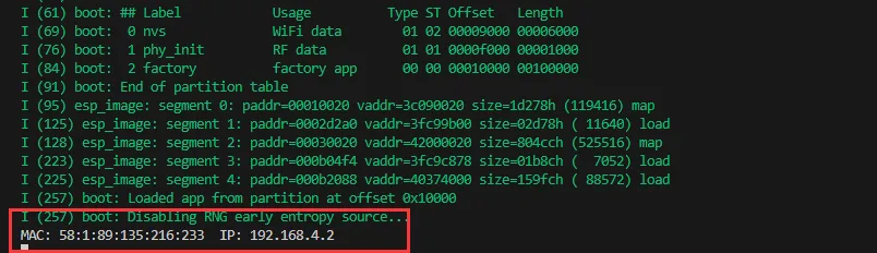
After flashing the program, open the serial terminal, if the device is successfully connected to the hotspot, the MAC address and IP address of the device will be output, as shown in the figure:
03_WIFI_STA
Description
- This example can configure the development board as a STA device to connect to a router, thereby enabling access to the system network.
Hardware Connection
- Connect the board to the computer using a USB cable
Code Analysis
-
In the file
esp_wifi_bsp.c, findssidandpassword, then modify them to the SSID and Password of an available router in your current environment.wifi_config_t wifi_config = {.sta = {.ssid = "PDCN",.password = "1234567890",},};
Operation Result
-
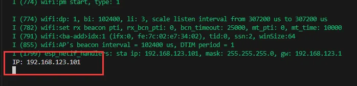
After flashing the program, open the serial terminal, if the device is successfully connected to the hotspot, the IP address obtained will be output, as shown in the figure:
04_BATT_PWR_Test
Description
- Demonstrates how to control the system power via the PWR button when powered by the lithium battery.
Hardware Connection
- Connect the board to the computer using a USB cable
Code Analysis
setup_ui(lv_ui *ui): Initializes the UI interface for visual control.BatteryMonitor batt_dev(ADC_CHANNEL_3,18,17): Initializes the control IO ports for the lithium battery.user_button_init(): Initializes the buttons and their trigger events.Custom_ButtonPWRLoopTask(void *arg): A task that waits for button event triggers.
Operation Result
-
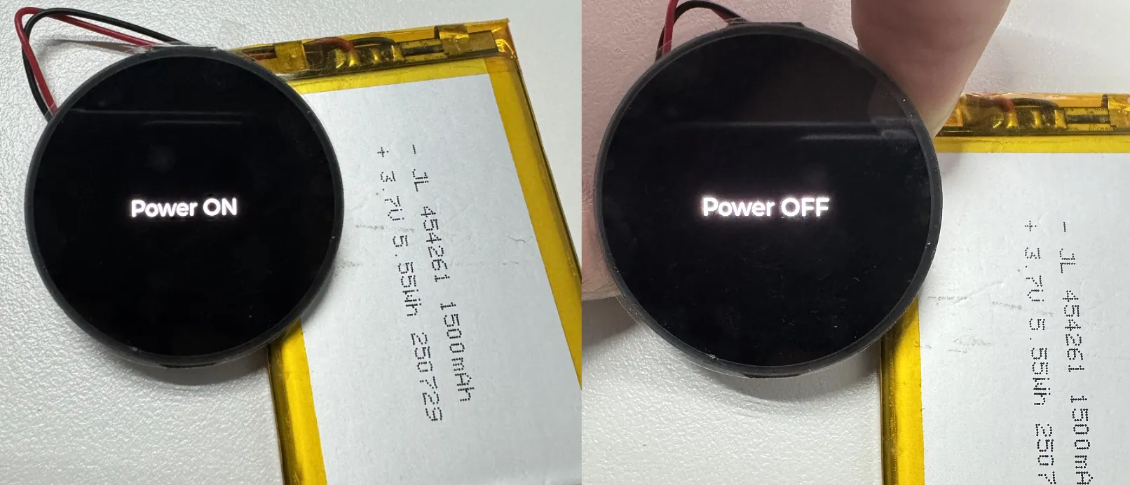
After the program is flashed, disconnect the USB power supply and connect the lithium battery. Power on by pressing and holding the PWR button, as shown in the figure:
tip- Press and hold the PWR button, wait for the screen to display "Power ON", which means that the startup is successful, and release the button
- Press and hold the PWR button again, wait for the screen to display "Power OFF", which means that the power is turned off successfully, and release the button
05_Audio_Test
Description
- Demonstrates how to capture microphone data, play sound, and other audio functions.
Hardware Connection
- Connect the board to the computer using a USB cable
Code Analysis
I2cMasterBus i2c_dev(ESP32_SCL_NUM,ESP32_SDA_NUM,0): Initializes the I2C bus.audio_dev = new I2sAudioCodec("S3_AMOLED_1_32"): Initializes the Audio Codec.audio_dev->I2sAudio_SetSpeakerVol(90): Sets the playback volume level.audio_dev->I2sAudio_SetMicGain(20): Sets the recording gain.
Operation Result
-
After the program is flashed, speak into the microphone. The speaker will automatically play the recorded sound. The screen display is as shown in the figure:
tip- Press and hold the BOOT button to play a piece of music
- If you feel the sound is too low, you can adjust the volume using
audio_dev->I2sAudio_SetSpeakerVol(90);, range 0-100
06_LVGL_V8_Test
Description
- Implements various multifunctional GUI interfaces on the screen by porting LVGL V8.
Hardware Connection
- Connect the board to the computer using a USB cable
Code Analysis
-
To perform a backlight test, locate the macro definition
#define BacklightTestEN 0in theuser_config.hfile and change its value to 1.#define BacklightTestEN 0 //Backlight Test
Operation Result
-
After the program is flashed, the device operation result is as follows:
07_LVGL_V9_Test
Description
- Implements various multifunctional GUI interfaces on the screen by porting LVGL V9.
Hardware Connection
- Connect the board to the computer using a USB cable
Code Analysis
-
To perform a backlight test, locate the macro definition
#define BacklightTestEN 0in theuser_config.hfile and change its value to 1.#define BacklightTestEN 0 //Backlight Test
Operation Result
-
After the program is flashed, the device operation result is as follows:
08_FactoryProgram
Description
- Comprehensive project, you can simply test the onboard hardware functions, or directly use the BIN firmware we provide for flashing.
Hardware Connection
- Connect the board to the computer using a USB cable
Operation Result
-
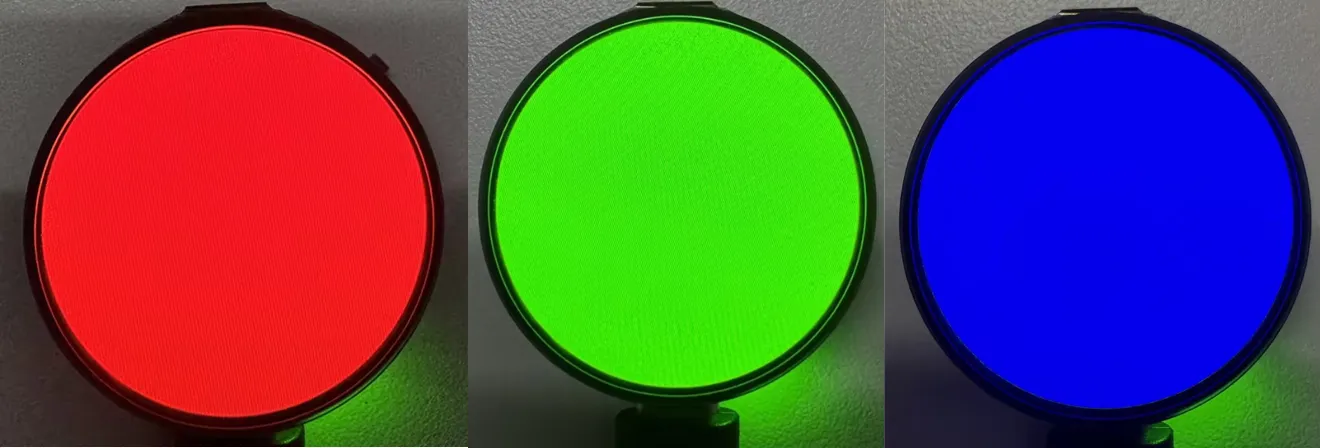
The display screen transitions through red, green, and blue colors (with a transition interval of 1.5 seconds), as shown in the figure:
-
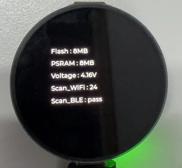
After the system finishes displaying the above colors, it will automatically enter the onboard hardware information interface, as shown in the figure:
-
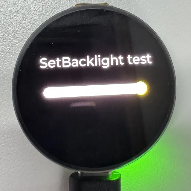
Click the BOOT button on the onboard hardware information interface to enter the backlight debugging interface, where the screen backlight can be controlled via the slider, as shown in the figure:
-
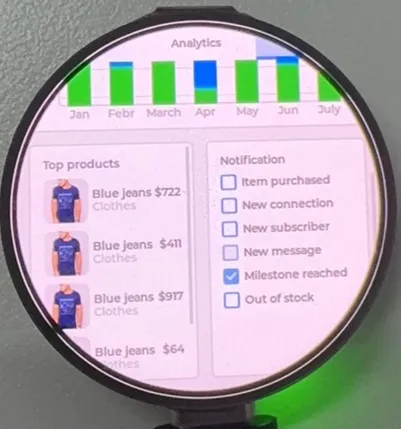
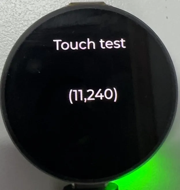
Click the BOOT button again to exit the backlight control interface, then click the PWR button to enter the Touch interface, as shown in the figure:
Touch coordinates are displayed on the screen.
-
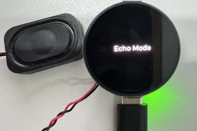
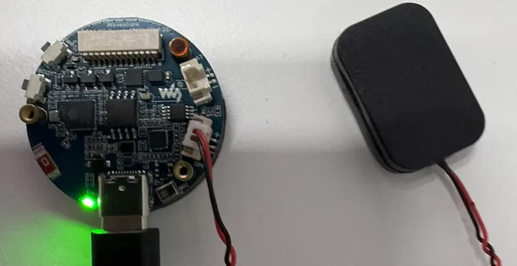
Use the audio function in a simple way, and the speaker wiring is as shown:
note- Speak into the MIC, and the speaker will play the received sound
- Hold down the BOOT button, and the speaker will play music
-
When using the lithium battery for power supply alone, the PWR button controls the power:
Press and hold the PWR button to turn on the system power; press and hold it again to shut down the system power.