ESP32-S3-Touch-AMOLED-2.16
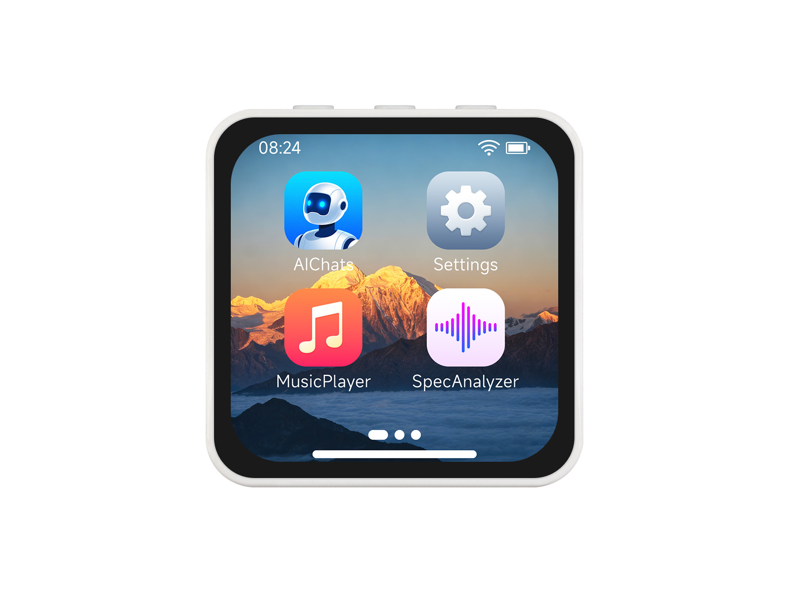
This product is a high-performance, highly integrated microcontroller development board designed by Waveshare. Despite its compact size, it features an onboard 2.16inch capacitive HD AMOLED screen, a highly integrated power management chip, a 6-axis IMU (3-axis accelerometer and 3-axis gyroscope), an RTC, a low-power audio codec chip, and echo cancellation circuitry, facilitating development and integration into end products.
| SKU | Product |
|---|---|
| 33969 | ESP32-S3-Touch-AMOLED-2.16 |
| 33970 | ESP32-S3-Touch-AMOLED-2.16-EN |
Features
- Powered by the ESP32-S3R8 high-performance Xtensa 32-bit LX7 dual-core processor, with a main frequency of up to 240 MHz
- Supports 2.4GHz Wi-Fi (802.11 b/g/n) and Bluetooth 5 (LE) with an onboard antenna
- Built-in 512KB SRAM and 384KB ROM, with stacked 8MB PSRAM and external 16MB Flash
- Features a Type-C interface, enhancing user convenience and device compatibility
- Onboard 2.16inch capacitive touch high-definition AMOLED display, 480 × 480 resolution, 16.7M colors, enabling clear display of color images
- Utilizes an AMOLED screen, offering higher contrast, wider viewing angles, rich colors, and fast response times for superior visual effects, along with advantages such as slim design, low power consumption, and flexibility
- Built-in CO5300 driver chip and CST9220 capacitive touch controller chip, communicating via QSPI and I2C interfaces respectively, minimizing the use of I/O pins
- Equipped with a dual-microphone array for audio algorithms such as noise reduction and echo cancellation, suitable for accurate speech recognition and near-field/far-field wake-up applications
- Onboard QMI8658 6-axis IMU (3-axis accelerometer and 3-axis gyroscope) enables motion posture detection, step counting, and other functions
- Onboard PWR and BOOT side buttons, configurable for custom function development
- Onboard 3.7V MX1.25 lithium battery charge/discharge interface
- The AXP2101 provides an efficient power management solution, supporting multiple configurable output voltages and integrating charging and battery management functions to help extend battery life
Onboard Resources
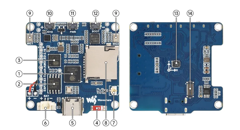
- ESP32-S3R8 Wi-Fi and Bluetooth SoC, up to 240MHz operating frequency, with onboard 8MB PSRAM
- 16MB NOR Flash
- AXP2101 Highly integrated power management chip
- Onboard Chip Antenna Supports 2.4GHz Wi-Fi (802.11 b/g/n) and Bluetooth 5 (LE)
- Type-C Port ESP32‑S3 USB port for programming and log output
- MX1.25 Lithium Battery Header MX1.25 2PIN connector for connecting a 3.7V lithium battery, supports charging and discharging
- IPEX 1 Antenna Connector Can be switched to an external antenna by changing the resistors
- TF Card Slot
- Dual-microphone Design Combined with echo cancellation circuitry for higher quality audio capture
- GPIO 18 Button Supports custom functions
- PWR Power Button Controls power on/off and supports custom functions
- BOOT Button Used for device startup and functional debugging
- QMI8658 6-axis IMU includes a 3-axis gyroscope and a 3-axis accelerometer
- Screen Interface
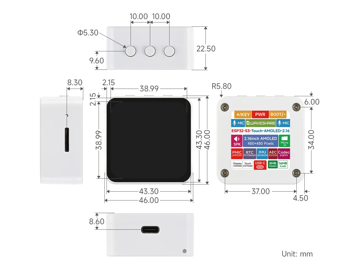
Dimensions
Development Methods
The ESP32-S3-Touch-AMOLED-2.16 supports two development frameworks: Arduino IDE and ESP-IDF, providing flexibility for developers to choose the tool that best fits their project requirements and personal preference.
Both development methods have their own advantages. Developers can choose based on their needs and skill levels. Arduino is simple to learn and quick to start, suitable for beginners and non-professionals. ESP-IDF provides more advanced development tools and stronger control capabilities, suitable for developers with professional backgrounds or higher performance requirements, and is more appropriate for complex project development.
-
Arduino IDE is a convenient, flexible, and easy-to-use open-source electronics prototyping platform. It requires minimal foundational knowledge, allowing for rapid development after a short learning period. Arduino has a huge global user community, providing a vast amount of open-source code, project examples, and tutorials, as well as a rich library ecosystem that encapsulates complex functions, enabling developers to implement various features rapidly. You can refer to the Working with Arduino to complete the initial setup, and the tutorial also provides related demos for reference.
-
ESP-IDF, short for Espressif IoT Development Framework, is a professional development framework launched by Espressif Systems for its ESP series of chips. It is based on C language development and includes compilers, debuggers, flashing tools, etc. It supports development via command line or integrated development environments (such as Visual Studio Code with the Espressif IDF plugin), which provides features like code navigation, project management, and debugging. We recommend using VS Code for development. For the specific configuration process, please refer to the Working with ESP-IDF. The tutorial also provides relevant demos for reference.