Working with Arduino
This chapter includes the following sections, please read as needed:
Arduino Getting Started Tutorial
New to Arduino ESP32 development and looking for a quick start? We have prepared a comprehensive Getting Started Tutorial for you.
- Section 0: Getting to Know ESP32
- Section 1: Installing and Configuring Arduino IDE
- Section 2: Arduino Basics
- Section 3: Digital Output/Input
- Section 4: Analog Input
- Section 5: Pulse Width Modulation (PWM)
- Section 6: Serial Communication (UART)
- Section 7: I2C Communication
- Section 8: SPI Communication
- Section 9: Wi-Fi Basics
- Section 10: Web Server
- Section 11: Bluetooth
- Section 12: LVGL GUI Development
- Section 13: Comprehensive Project
Note: This tutorial uses the ESP32-S3-Zero as a reference example, and all hardware code is based on its pinout. Before you start, we recommend checking the pinout of your development board to ensure the pin configuration is correct.
Setting Up Development Environment
1. Installing and Configuring Arduino IDE
Please refer to the tutorial Installing and Configuring Arduino IDE Tutorial to download and install the Arduino IDE and add ESP32 support.
2. Installing Libraries
To run the demo, you need to install the corresponding library.
You can click this link to download the example package for the ESP32-S3-Touch-LCD-4.3C development board. The arduino\libraries directory within the package already includes all the library files required for this tutorial.
| Library/File Name | Description | Version | Installation Method |
|---|---|---|---|
| lvgl | LVGL graphics library | v8.4.0 | Install via library manager or manually |
| lv_conf.h | LVGL configuration file | —— | Install manually |
There are strong dependencies between versions of LVGL and its driver libraries. For example, a driver written for LVGL v8 may not be compatible with LVGL v9. To ensure stable reproduction of the examples, it is recommended to use the specific versions listed in the table above. Mixing different library versions may cause compilation failures or runtime exceptions.
Installation Steps:
-
Navigate to the downloaded example package.
-
Copy all folders (such as lvgl and lv_conf.h) from the
arduino\librariesdirectory to the Arduino libraries folder.infoThe path to the Arduino libraries folder is typically:
c:\Users\<Username>\Documents\Arduino\libraries.You can also locate it within the Arduino IDE via File > Preferences, by checking the "Sketchbook location". The library folder is the
librariesfolder under this path. -
For other installation methods, please refer to: Arduino Library Management Tutorial.
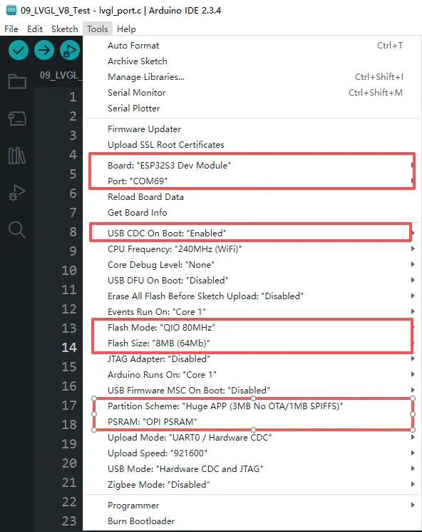
3. Arduino Project Parameter Settings
Example
The Arduino examples are located in the arduino/examples directory of the example package.
| Demo | Basic Program Description | Dependency Library |
|---|---|---|
| 01_i2c | Test I2C functionality | - |
| 02_rtc | Test RTC functionality | - |
| 03_lcd | Test LCD functionality | - |
| 04_isolation_io | Test ISOLATION_IO functionality | - |
| 05_sd | Test TF card functionality | - |
| 06_touch | Test touch screen functionality | - |
| 07_display_bmp | Display images from TF card | - |
| 08_wifi_scan | Scan nearby Wi-Fi networks and display names | - |
| 09_wifi_sta | Test STA mode | - |
| 10_wifi_ap | Test AP mode | - |
| 11_speaker_microphone | Test microphone input and speaker playback | - |
| 12_lvgl_transplant | LVGL demo test | LVGL |
| 13_lvgl_btn | Draw a button to control GPIO output | LVGL |
| 14_lvgl_slider | Draw a slider to control backlight & GPIO, display battery voltage | LVGL |
| 15_udp_tcp_ntp | Implement UDP/TCP communication and NTP time sync | LVGL |
01_i2c
This example demonstrates how to periodically control the LCD backlight's on/off state via I2C, creating a flashing effect, using an I/O expansion chip.
Hardware Connection
- Connect the board to the computer using a USB cable
Code
01_i2c.ino
#include "src/io_extension/io_extension.h"

void setup() {
  // Initialize the IO EXTENSION device for I2C communication.
  DEV_I2C_Init();
  IO_EXTENSION_Init();
  delay(10);
}

void loop() {
  // Turn on the LCD backlight by setting IO_EXTENSION_IO_2 high.
  IO_EXTENSION_Output(IO_EXTENSION_IO_2, 1);
  delay(500);  // Wait for 500 milliseconds.

  // Turn off the LCD backlight by setting IO_EXTENSION_IO_2 low.
  IO_EXTENSION_Output(IO_EXTENSION_IO_2, 0);
  delay(500);  // Wait for 500 milliseconds.
}
Code Analysis
-
setup():- This function initializes the I2C communication and the I/O expansion chip, setting the IO_EXTENSION_IO_2 pin to output mode.
-
loop():- The IO_EXTENSION_Output function is used to toggle the IO_EXTENSION_IO_2 pin's state between high (1) and low (0), turning the LCD backlight on and off to create a periodic flashing effect once per second.
Operation Result
- The screen shows nothing, and the connected LED light flashes at a frequency of 1 Hz.
02_rtc
This example demonstrates how to use the onboard PCF85063 RTC chip to implement a real-time clock display and alarm reminder functionality.
Hardware Connection
- Connect the board to the computer using a USB cable
Code
02_rtc.ino
#include "src/io_extension/io_extension.h"       // IO extension control (e.g., external interrupt input)
#include "src/rtc_pcf85063a/rtc_pcf85063a.h"     // PCF85063A RTC driver

// Initial RTC time to be set
static datetime_t Set_Time = {
    .year = 2025,
    .month = 07,
    .day = 30,
    .dotw = 3,   // Day of the week: 0 = Sunday
    .hour = 9,
    .min = 0,
    .sec = 0
};

// Alarm time to be set
static datetime_t Set_Alarm_Time = {
    .year = 2025,
    .month = 07,
    .day = 30,
    .dotw = 3,
    .hour = 9,
    .min = 0,
    .sec = 2
};

char datetime_str[256];  // Buffer to store formatted date-time string

void setup() {
  // Start Serial
  Serial.begin(115200); // Initialize serial communication at 115200 baud rate

  // Initialize the I2C interface
  DEV_I2C_Init();

  // Initialize external IO extension chip
  IO_EXTENSION_Init();

  // Initialize PCF85063A RTC
  PCF85063A_Init();

  // Set current time
  PCF85063A_Set_All(Set_Time);

  // Set alarm time
  PCF85063A_Set_Alarm(Set_Alarm_Time);

  // Enable alarm interrupt
  PCF85063A_Enable_Alarm();

}

datetime_t Now_time;
void loop() {
  // Read current time from RTC
  PCF85063A_Read_now(&Now_time);

  // Format current time as a string
  datetime_to_str(datetime_str, Now_time);
  printf("Now_time is %s\r\n", datetime_str);

  // Poll external IO pin for alarm (low level = alarm triggered)
  if (IO_EXTENSION_Rtc_Int_Read() == 0)
  {
      // Re-enable alarm if repeated alarms are required
      PCF85063A_Enable_Alarm();
      printf("The alarm clock goes off.\r\n");
  }
  delay(1000);
}
Code Analysis
-
setup():- Initializes the serial port, I2C bus, and the RTC chip, sets the initial time and alarm, preparing the system for operation.
-
loop():- Continuously reads and prints the current time while checking if the alarm has been triggered, implementing the real-time clock and alarm reminder functionality.
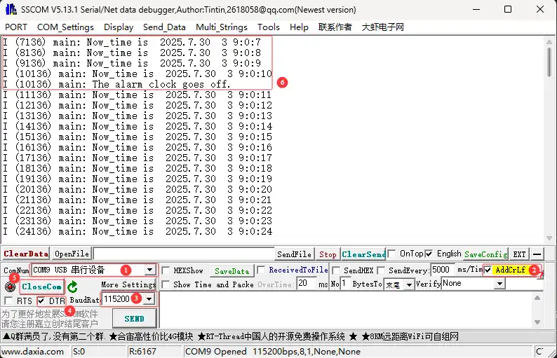
Operation Result
-
Open the serial port debugging assistant to send a message to the ESP32-S3-Touch-LCD-4.3C device, and the device will return the received message to the serial port debugging assistant
03_lcd
This example demonstrates how to initialize the LCD and display various graphics, text, and images.
Hardware Connection
- Connect the board to the computer using a USB cable
Code
03_lcd.ino
/*
* The LCD parameters and GPIO number used by this example can be changed in
* [rgb_lcd_port.h](components/rgb_lcd_port.h). Especially, please pay attention
* to the **vendor specific initialization**, it can be different between
* manufacturers and should consult the LCD supplier for initialization sequence
* code.
*/
#include "src/rgb_lcd_port/rgb_lcd_port.h"          // Header for Waveshare RGB LCD driver
#include "src/rgb_lcd_port/gui_paint/gui_paint.h"   // Header for graphical drawing functions
#include "src/rgb_lcd_port/image/image.h"           // Header for image resources

#define ROTATE ROTATE_0//rotate = 0, 90, 180, 270

void setup() {
  // put your setup code here, to run once:
  Serial.begin(115200);
  DEV_I2C_Init();
  IO_EXTENSION_Init();
  // Initialize the Waveshare ESP32-S3 RGB LCD
  waveshare_esp32_s3_rgb_lcd_init();
  // Turn on the LCD backlight
  wavesahre_rgb_lcd_bl_on();
  UDOUBLE Imagesize = EXAMPLE_LCD_H_RES * EXAMPLE_LCD_V_RES * 2; // Each pixel takes 2 bytes in RGB565
  UBYTE *BlackImage;
  if ((BlackImage = (UBYTE *)malloc(Imagesize)) == NULL) // Allocate memory
  {
      printf("Failed to apply for black memory...\r\n");
      exit(0); // Exit the program if memory allocation fails
  }
  // Create a new image canvas and set its background color to white
    Paint_NewImage(BlackImage, EXAMPLE_LCD_H_RES, EXAMPLE_LCD_V_RES, 0, WHITE);

    // Set the canvas scale
    Paint_SetScale(65);
    Paint_SetRotate(ROTATE);
    // Clear the canvas and fill it with a white background
    Paint_Clear(WHITE);
    if (ROTATE == ROTATE_0 || ROTATE == ROTATE_180)
    {
        // Draw gradient color stripes using RGB565 format
        // From red to blue
        Paint_DrawRectangle(1, 1, 50, 480, 0xF800, DOT_PIXEL_1X1, DRAW_FILL_FULL);
        Paint_DrawRectangle(51, 1, 100, 480, 0x7800, DOT_PIXEL_1X1, DRAW_FILL_FULL);
        Paint_DrawRectangle(101, 1, 150, 480, 0x3800, DOT_PIXEL_1X1, DRAW_FILL_FULL);
        Paint_DrawRectangle(151, 1, 200, 480, 0x1800, DOT_PIXEL_1X1, DRAW_FILL_FULL);
        Paint_DrawRectangle(201, 1, 250, 480, 0x0800, DOT_PIXEL_1X1, DRAW_FILL_FULL);


        Paint_DrawRectangle(251, 1, 300, 480, 0x07E0, DOT_PIXEL_1X1, DRAW_FILL_FULL);
        Paint_DrawRectangle(301, 1, 350, 480, 0x03E0, DOT_PIXEL_1X1, DRAW_FILL_FULL);
        Paint_DrawRectangle(351, 1, 400, 480, 0x01E0, DOT_PIXEL_1X1, DRAW_FILL_FULL);
        Paint_DrawRectangle(401, 1, 450, 480, 0x00E0, DOT_PIXEL_1X1, DRAW_FILL_FULL);
        Paint_DrawRectangle(451, 1, 500, 480, 0x0060, DOT_PIXEL_1X1, DRAW_FILL_FULL);
        Paint_DrawRectangle(501, 1, 550, 480, 0x0020, DOT_PIXEL_1X1, DRAW_FILL_FULL);

        Paint_DrawRectangle(551, 1, 600, 480, 0x001F, DOT_PIXEL_1X1, DRAW_FILL_FULL);
        Paint_DrawRectangle(601, 1, 650, 480, 0x000F, DOT_PIXEL_1X1, DRAW_FILL_FULL);
        Paint_DrawRectangle(651, 1, 700, 480, 0x0007, DOT_PIXEL_1X1, DRAW_FILL_FULL);
        Paint_DrawRectangle(701, 1, 750, 480, 0x0003, DOT_PIXEL_1X1, DRAW_FILL_FULL);
        Paint_DrawRectangle(751, 1, 800, 480, 0x0001, DOT_PIXEL_1X1, DRAW_FILL_FULL);

        // Display the gradient on the screen
        wavesahre_rgb_lcd_display(BlackImage);
        vTaskDelay(1000);

        Paint_Clear(WHITE);
        // Draw points with increasing sizes
        Paint_DrawPoint(2, 18, BLACK, DOT_PIXEL_1X1, DOT_FILL_RIGHTUP);
        Paint_DrawPoint(2, 20, BLACK, DOT_PIXEL_2X2, DOT_FILL_RIGHTUP);
        Paint_DrawPoint(2, 23, BLACK, DOT_PIXEL_3X3, DOT_FILL_RIGHTUP);
        Paint_DrawPoint(2, 28, BLACK, DOT_PIXEL_4X4, DOT_FILL_RIGHTUP);
        Paint_DrawPoint(2, 33, BLACK, DOT_PIXEL_5X5, DOT_FILL_RIGHTUP);

        // Draw solid and dotted lines
        Paint_DrawLine(20, 5, 80, 65, MAGENTA, DOT_PIXEL_2X2, LINE_STYLE_SOLID);
        Paint_DrawLine(20, 65, 80, 5, MAGENTA, DOT_PIXEL_2X2, LINE_STYLE_SOLID);
        Paint_DrawLine(148, 35, 208, 35, CYAN, DOT_PIXEL_1X1, LINE_STYLE_DOTTED);
        Paint_DrawLine(178, 5, 178, 65, CYAN, DOT_PIXEL_1X1, LINE_STYLE_DOTTED);

        // Draw rectangles (empty and filled)
        Paint_DrawRectangle(20, 5, 80, 65, RED, DOT_PIXEL_2X2, DRAW_FILL_EMPTY);
        Paint_DrawRectangle(85, 5, 145, 65, BLUE, DOT_PIXEL_2X2, DRAW_FILL_FULL);

        // Draw circles (empty and filled)
        Paint_DrawCircle(178, 35, 30, GREEN, DOT_PIXEL_1X1, DRAW_FILL_EMPTY);
        Paint_DrawCircle(240, 35, 30, GREEN, DOT_PIXEL_1X1, DRAW_FILL_FULL);

        // Draw text and numbers
        Paint_DrawString_EN(1, 70, "AaBbCc123", &Font16, RED, WHITE);
        Paint_DrawNum(1, 100, 9.87654321, &Font20, 7, WHITE, BLACK);
        Paint_DrawString_EN(1, 130, "AaBbCc123", &Font20, 0x000f, 0xfff0);
        Paint_DrawString_EN(1, 160, "AaBbCc123", &Font24, RED, WHITE);
        Paint_DrawString_CN(1, 190, "Hello Abc", &Font24CN, WHITE, BLUE);

        // Update the display with the newly drawn elements (currently displaying BlackImage)
        wavesahre_rgb_lcd_display(BlackImage);
        vTaskDelay(1000); // Delay for 1000ms to allow the screen to update

        // Draw a bitmap at coordinates (0,0) with size 800x480 using the provided gImage_Bitmap
        Paint_BmpWindows(0, 0, gImage_Bitmap, 800, 480);

        // Update the screen with the updated image (BlackImage is the framebuffer being drawn to)
        wavesahre_rgb_lcd_display(BlackImage); // Refresh the display with the new content
        vTaskDelay(1000); // Delay for 1000ms to allow the screen to update

        // Draw an image resource gImage_picture at coordinates (0,0) with size 800x480
        Paint_DrawImage(gImage_picture, 0, 0, 800, 480);

        // Optionally, you can also call this to draw the bitmap, though it's commented out here:
        // Paint_DrawBitMap(gImage_picture);

        // Update the screen with the new image (BlackImage is the framebuffer being drawn to)
        wavesahre_rgb_lcd_display(BlackImage); // Refresh the display to show the updated image

    }
    else
    {
        // Draw gradient color stripes using RGB565 format
        // From red to blue
        Paint_DrawRectangle(1, 1, 480, 50, 0xF800, DOT_PIXEL_1X1, DRAW_FILL_FULL);
        Paint_DrawRectangle(1, 51, 480, 100, 0x7800, DOT_PIXEL_1X1, DRAW_FILL_FULL);
        Paint_DrawRectangle(1, 101, 480, 150, 0x3800, DOT_PIXEL_1X1, DRAW_FILL_FULL);
        Paint_DrawRectangle(1, 151, 480, 200, 0x1800, DOT_PIXEL_1X1, DRAW_FILL_FULL);
        Paint_DrawRectangle(1, 201, 480, 250, 0x0800, DOT_PIXEL_1X1, DRAW_FILL_FULL);


        Paint_DrawRectangle(1, 251, 480, 300, 0x07E0, DOT_PIXEL_1X1, DRAW_FILL_FULL);
        Paint_DrawRectangle(1, 301, 480, 350, 0x03E0, DOT_PIXEL_1X1, DRAW_FILL_FULL);
        Paint_DrawRectangle(1, 351, 480, 400, 0x01E0, DOT_PIXEL_1X1, DRAW_FILL_FULL);
        Paint_DrawRectangle(1, 401, 480, 450, 0x00E0, DOT_PIXEL_1X1, DRAW_FILL_FULL);
        Paint_DrawRectangle(1, 451, 480, 500, 0x0060, DOT_PIXEL_1X1, DRAW_FILL_FULL);
        Paint_DrawRectangle(1, 501, 480, 550, 0x0020, DOT_PIXEL_1X1, DRAW_FILL_FULL);

        Paint_DrawRectangle(1, 550, 480, 600, 0x001F, DOT_PIXEL_1X1, DRAW_FILL_FULL);
        Paint_DrawRectangle(1, 600, 480, 650, 0x000F, DOT_PIXEL_1X1, DRAW_FILL_FULL);
        Paint_DrawRectangle(1, 650, 480, 700, 0x0007, DOT_PIXEL_1X1, DRAW_FILL_FULL);
        Paint_DrawRectangle(1, 700, 480, 750, 0x0003, DOT_PIXEL_1X1, DRAW_FILL_FULL);
        Paint_DrawRectangle(1, 750, 480, 800, 0x0001, DOT_PIXEL_1X1, DRAW_FILL_FULL);

        // Display the gradient on the screen
        wavesahre_rgb_lcd_display(BlackImage);
        vTaskDelay(1000);

        Paint_Clear(WHITE);
        // Draw points with increasing sizes
        Paint_DrawPoint(2, 18, BLACK, DOT_PIXEL_1X1, DOT_FILL_RIGHTUP);
        Paint_DrawPoint(2, 20, BLACK, DOT_PIXEL_2X2, DOT_FILL_RIGHTUP);
        Paint_DrawPoint(2, 23, BLACK, DOT_PIXEL_3X3, DOT_FILL_RIGHTUP);
        Paint_DrawPoint(2, 28, BLACK, DOT_PIXEL_4X4, DOT_FILL_RIGHTUP);
        Paint_DrawPoint(2, 33, BLACK, DOT_PIXEL_5X5, DOT_FILL_RIGHTUP);

        // Draw solid and dotted lines
        Paint_DrawLine(20, 5, 80, 65, MAGENTA, DOT_PIXEL_2X2, LINE_STYLE_SOLID);
        Paint_DrawLine(20, 65, 80, 5, MAGENTA, DOT_PIXEL_2X2, LINE_STYLE_SOLID);
        Paint_DrawLine(148, 35, 208, 35, CYAN, DOT_PIXEL_1X1, LINE_STYLE_DOTTED);
        Paint_DrawLine(178, 5, 178, 65, CYAN, DOT_PIXEL_1X1, LINE_STYLE_DOTTED);

        // Draw rectangles (empty and filled)
        Paint_DrawRectangle(20, 5, 80, 65, RED, DOT_PIXEL_2X2, DRAW_FILL_EMPTY);
        Paint_DrawRectangle(85, 5, 145, 65, BLUE, DOT_PIXEL_2X2, DRAW_FILL_FULL);

        // Draw circles (empty and filled)
        Paint_DrawCircle(178, 35, 30, GREEN, DOT_PIXEL_1X1, DRAW_FILL_EMPTY);
        Paint_DrawCircle(240, 35, 30, GREEN, DOT_PIXEL_1X1, DRAW_FILL_FULL);

        // Draw text and numbers
        Paint_DrawString_EN(1, 70, "AaBbCc123", &Font16, RED, WHITE);
        Paint_DrawNum(1, 100, 9.87654321, &Font20, 7, WHITE, BLACK);
        Paint_DrawString_EN(1, 130, "AaBbCc123", &Font20, 0x000f, 0xfff0);
        Paint_DrawString_EN(1, 160, "AaBbCc123", &Font24, RED, WHITE);
        Paint_DrawString_CN(1, 190, "Hello Abc", &Font24CN, WHITE, BLUE);

        // Update the display with the newly drawn elements (currently displaying BlackImage)
        wavesahre_rgb_lcd_display(BlackImage);
        vTaskDelay(1000); // Delay for 1000ms to allow the screen to update

        // Draw a bitmap at coordinates (0,0) with size 800x480 using the provided gImage_Bitmap
        Paint_BmpWindows(0, 0, gImage_Bitmap_90, 480, 800);

        // Update the screen with the updated image (BlackImage is the framebuffer being drawn to)
        wavesahre_rgb_lcd_display(BlackImage); // Refresh the display with the new content
        vTaskDelay(1000); // Delay for 1000ms to allow the screen to update

        // Draw an image resource gImage_picture at coordinates (0,0) with size 800x480
        Paint_DrawImage(gImage_picture_90, 0, 0, 480, 800);

        // Optionally, you can also call this to draw the bitmap, though it's commented out here:
        // Paint_DrawBitMap(gImage_picture);

        // Update the screen with the new image (BlackImage is the framebuffer being drawn to)
        wavesahre_rgb_lcd_display(BlackImage); // Refresh the display to show the updated image


    }
}

void loop() {
  // put your main code here, to run repeatedly:

}
Code Analysis
-
setup():- Completes LCD initialization, display memory allocation, and sequentially demonstrates the display of color gradients, points and lines, rectangles and circles, text and numbers, and finally images.
-
Paint_NewImage():- Canvas creation: Sets up memory as the drawing frame buffer.
-
Paint_DrawRectangle():- Rectangle drawing: Used to draw color stripes, etc.
-
Paint_DrawString_EN():- Text rendering: Used to draw English character strings. Each function draws different elements, and then wavesahre_rgb_lcd_display() is called to refresh the screen.
Operation Result
- The screen first displays a color gradient bar, followed sequentially by points, lines, rectangles, circles, text, numbers, and finally, two images displayed full-screen.
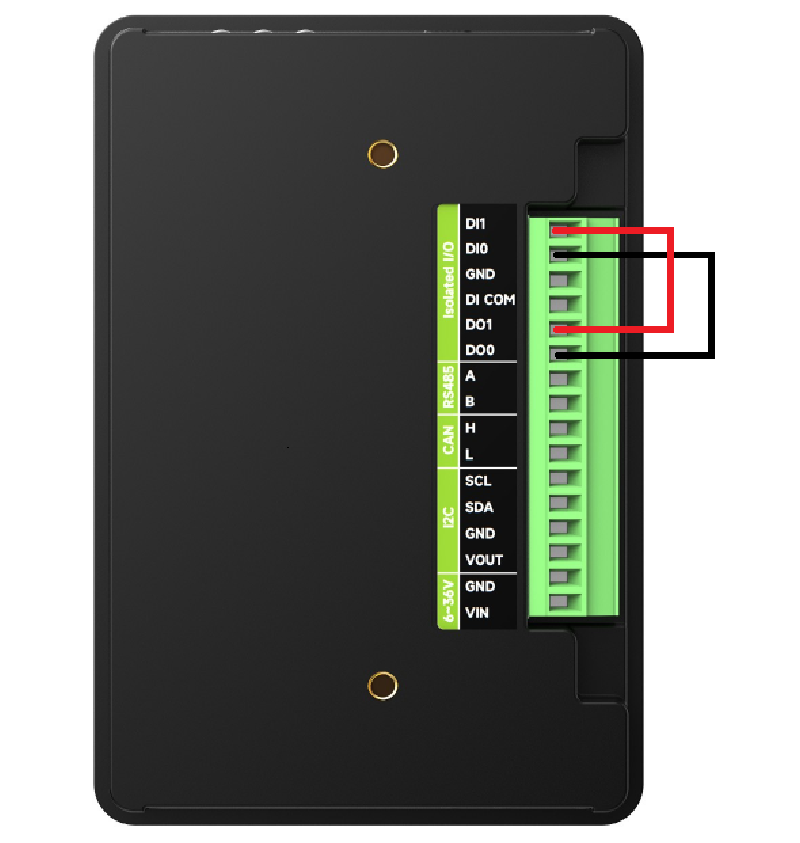
04_isolation_io
This example verifies the isolation I/O functionality using the display.
Hardware Connection
- Connect the board to the computer using a USB cable
- Connect DO0 -> DI0 and DO1 -> DI1 on the back of the development board.
Code
04_isolation_io.ino
/*
* The LCD parameters and GPIO number used by this example can be changed in
* [rgb_lcd_port.h](components/rgb_lcd_port.h). Especially, please pay attention
* to the **vendor specific initialization**, it can be different between
* manufacturers and should consult the LCD supplier for initialization sequence
* code.
*/
#include "src/rgb_lcd_port/rgb_lcd_port.h"          // Header for Waveshare RGB LCD driver
#include "src/rgb_lcd_port/gui_paint/gui_paint.h"   // Header for graphical drawing functions
#include "src/rgb_lcd_port/image/image.h"           // Header for image resources

#define ROTATE ROTATE_0//rotate = 0, 90, 180, 270

void setup() {
  // put your setup code here, to run once:
  Serial.begin(115200);
  DEV_I2C_Init();
  IO_EXTENSION_Init();
  IO_EXTENSION_IO_Mode(0xDE); // Set EXIO0 and EXIO5 as input modes.

  // Initialize the Waveshare ESP32-S3 RGB LCD
  waveshare_esp32_s3_rgb_lcd_init();
  // Turn on the LCD backlight
  wavesahre_rgb_lcd_bl_on();

  UDOUBLE Imagesize = EXAMPLE_LCD_H_RES * EXAMPLE_LCD_V_RES * 2; // Each pixel takes 2 bytes in RGB565
  UBYTE *BlackImage;
  if ((BlackImage = (UBYTE *)malloc(Imagesize)) == NULL) // Allocate memory
  {
      printf("Failed to apply for black memory...\r\n");
      exit(0); // Exit the program if memory allocation fails
  }
  // Create a new image canvas and set its background color to white
    Paint_NewImage(BlackImage, EXAMPLE_LCD_H_RES, EXAMPLE_LCD_V_RES, 0, WHITE);

    // Set the canvas scale
    Paint_SetScale(65);
    Paint_SetRotate(ROTATE);
    // Clear the canvas and fill it with a white background
    Paint_Clear(WHITE);
    uint8_t io[2] = {0}, DI_flag = 0, num = 0;
    while (1)
    {
        IO_EXTENSION_Output(DO0, 1);
        IO_EXTENSION_Output(DO1, 0);
        vTaskDelay(10 / portTICK_PERIOD_MS);
        io[0] = IO_EXTENSION_Input(DI0); // Read DI0
        io[1] = IO_EXTENSION_Input(DI1); // Read DI1
        // Check if both pins match expected values
        if (io[0] == 1 && io[1] == 0)
        {
            DI_flag++; // Increment DI flag
        }

        IO_EXTENSION_Output(DO0, 0);
        IO_EXTENSION_Output(DO1, 1);
        vTaskDelay(10 / portTICK_PERIOD_MS);
        io[0] = IO_EXTENSION_Input(DI0); // Read DI0
        io[1] = IO_EXTENSION_Input(DI1); // Read DI1
        // Check again if both pins match expected values
        if (io[0] == 0 && io[1] == 1)
        {
            DI_flag++; // Increment DI flag
        }
        printf("DI_flag:%d\r\n",DI_flag);
        // If both conditions are met, DI & DO are working
        if (DI_flag >= 2)
        {
            printf("DI & DO OK!!!\r\n"); // DI and DO are functioning properly
            Paint_Clear(GREEN);
            // Display the gradient on the screen
            wavesahre_rgb_lcd_display(BlackImage);
            break;
        }
        else
        {
            num++;        // Add 1 to the count
            DI_flag=0;
            if (num == 3) // If the test fails three times, we quit
            {
                printf("DI & DO Failure!!!\r\n"); // DI and DO are not functioning
                Paint_Clear(RED);
                // Display the gradient on the screen
                wavesahre_rgb_lcd_display(BlackImage);
                break;
            }
        }
    }
}

void loop() {
  // put your main code here, to run repeatedly:

}
Code Analysis
-
setup():- The
setup()function initializes the serial port, I2C bus, I/O expansion chip, and LCD screen. It then tests the DI/DO functionality by controlling the DO pins and reading the state of the DI pins. Based on the test result, it displays green (test passed) or red (test failed) on the RGB LCD screen.
- The
-
Serial.begin(115200):- Initializes serial communication (for printing debug information, baud rate 115200).
-
DEV_I2C_Init():- Initializes the I2C bus (typically used for connecting sensors, displays, etc.).
-
IO_EXTENSION_Init():- Initializes the I/O expansion chip (to extend more GPIOs, such as DI/DO).
Operation Result
- After successful flashing, the screen will display red or green depending on the wiring on the back.
- When wired correctly, the screen displays green.
- When wired incorrectly, the screen displays red.
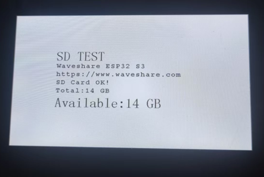
05_sd
This example displays the mounting status of the TF card on the screen.
Hardware Connection
- Connect the board to the computer using a USB cable
- Insert the TF card into ESP32-S3-Touch-LCD-4.3C
Code
05_sd.ino
/*
* Mount a TF card, output related parameters via serial, unmount the TF card,
* and display memory information on the screen.
*/
#include "src/rgb_lcd_port/rgb_lcd_port.h"          // Header for Waveshare RGB LCD driver
#include "src/rgb_lcd_port/gui_paint/gui_paint.h"   // Header for graphical drawing functions
#include "src/rgb_lcd_port/image/image.h"           // Header for image resources
#include "src/user_sd/user_sd.h"              // Header for TF card operations

void setup() {
  // put your setup code here, to run once:
  Serial.begin(115200);
  DEV_I2C_Init();
  IO_EXTENSION_Init();
  delay(10);
  IO_EXTENSION_Output(IO_EXTENSION_IO_4, 1);  // Set CS (chip select) pin high

  // Initialize the Waveshare ESP32-S3 RGB LCD
  waveshare_esp32_s3_rgb_lcd_init();
  // Turn on the LCD backlight
  wavesahre_rgb_lcd_bl_on();
  UDOUBLE Imagesize = EXAMPLE_LCD_H_RES * EXAMPLE_LCD_V_RES * 2; // Each pixel takes 2 bytes in RGB565
  UBYTE *BlackImage;
  if ((BlackImage = (UBYTE *)heap_caps_malloc(Imagesize, MALLOC_CAP_SPIRAM)) == NULL) // Allocate memory
  {
      printf("Failed to apply for black memory...\r\n");
      exit(0); // Exit the program if memory allocation fails
  }
  // Create a new image canvas and set its background color to white
  Paint_NewImage(BlackImage, EXAMPLE_LCD_H_RES, EXAMPLE_LCD_V_RES, 0, WHITE);

  // Set the canvas scale
  Paint_SetScale(65);
  Paint_Clear(BLACK);                // Clear the canvas with a black background

  // Draw static text on the canvas
  Paint_DrawString_EN(150, 130, "TF TEST", &Font48, CYAN, BLACK);
  Paint_DrawString_EN(150, 180, "Waveshare ESP32 S3", &Font24, CYAN, BLACK);
  Paint_DrawString_EN(150, 210, "https://www.waveshare.com", &Font24, CYAN, BLACK);
  char Total[100], Available[100]; // Buffers for formatted text
  if (sd_mmc_init() == ESP_OK) // Initialize TF card
  {
      Paint_DrawString_EN(150, 240, "TF Card OK!", &Font24, CYAN, BLACK); // Indicate TF card success

      uint64_t total, available; // Variables to store total and available space
      read_sd_capacity(&total, &available); // Read TF card capacity
      printf("Total:%d MB,Available:%d MB\r\n", (int)total / 1024, (int)available / 1024);

      // Format total space into a human-readable string
      if (((int)total / 1024) > 1024)
          sprintf(Total, "Total:%d GB", (int)total / 1024 / 1024);
      else
          sprintf(Total, "Total:%d MB", (int)total / 1024);

      // Format available space into a human-readable string
      if (((int)available / 1024) > 1024)
          sprintf(Available, "Available:%d GB", (int)available / 1024 / 1024);
      else
          sprintf(Available, "Available:%d MB", (int)available / 1024);

      // Draw the total and available space information on the canvas
      Paint_DrawString_EN(150, 270, Total, &Font24, CYAN, BLACK);
      Paint_DrawString_EN(150, 300, Available, &Font48, CYAN, BLACK);

      printf("Filesystem unmount\r\n");
      sd_mmc_unmount(); // Unmount the TF card
  }
  else
      Paint_DrawString_EN(150, 240, "TF Card Fail!", &Font24, CYAN, BLACK);

  // Display the prepared canvas on the LCD
  wavesahre_rgb_lcd_display(BlackImage);
}

void loop() {
  // put your main code here, to run repeatedly:

}
Code Analysis
-
setup():- Responsible for initializing all necessary hardware and communication interfaces, including the serial port, I2C bus, I/O expansion chip, and LCD screen. It then performs the TF card test: attempts to mount the TF card, and if successful, reads, calculates, and displays its total and available capacity information on the LCD screen and serial port, before immediately unmounting the TF card.
-
sd_mmc_init():- Attempts to mount the TF card file system.
-
read_sd_capacity():- Reads the total and available storage space from the mounted TF card.
-
sd_mmc_unmount():- Unmounts the TF card file system, releasing related resources.
Operation Result
-
After successful flashing, the screen displays the TF card capacity. If no TF card is inserted, it displays* TF Card Fail!
06_touch
This example demonstrates how to use 5-point touch.
Hardware Connection
- Connect the board to the computer using a USB cable
Code
06_touch.ino
/*
* Performs a five-point touch test and demonstrates basic usage of double buffering.
*/
#include "src/rgb_lcd_port/rgb_lcd_port.h"          // Header for Waveshare RGB LCD driver
#include "src/rgb_lcd_port/gui_paint/gui_paint.h"   // Header for graphical drawing functions
#include "src/gt911/gt911.h"           // Header for touch screen operations (GT911)

void setup() {
  touch_gt911_point_t point_data;  // Structure to store touch point data

  Serial.begin(115200);
  DEV_I2C_Init();
  IO_EXTENSION_Init();
  // Initialize the GT911 touch screen controller
  touch_gt911_init(DEV_I2C_Get_Bus_Device());

  // Initialize the Waveshare ESP32-S3 RGB LCD
  waveshare_esp32_s3_rgb_lcd_init();
  // Turn on the LCD backlight
  wavesahre_rgb_lcd_bl_on();
  // Frame buffer pointers for double buffering
  void *buf1 = NULL;
  void *buf2 = NULL;

  // Retrieve pointers to the frame buffers
  waveshare_get_frame_buffer(&buf1, &buf2);
  if (buf1 == NULL || buf2 == NULL) {
      printf("Error: buf1 and buf2 are NULL!\n");
      return;
  }

  // Initialize the graphics canvas with buf2
  Paint_NewImage((uint8_t *)buf2, EXAMPLE_LCD_H_RES, EXAMPLE_LCD_V_RES, 0, WHITE);

  // Set the scale for the graphical canvas
  Paint_SetScale(65);

  // Clear the canvas and fill it with a white background
  Paint_Clear(WHITE);

  // Copy buf2 content to buf1 to sync buffers
  memcpy(buf1, buf2, EXAMPLE_LCD_H_RES * EXAMPLE_LCD_V_RES * 2);

  // Display the initial blank screen on the LCD
  wavesahre_rgb_lcd_display((uint8_t *)buf1);

  // Arrays to store previous touch point positions and their active states
  static uint16_t prev_x[ESP_LCD_TOUCH_MAX_POINTS];
  static uint16_t prev_y[ESP_LCD_TOUCH_MAX_POINTS];
  static bool active[ESP_LCD_TOUCH_MAX_POINTS];  // Track if a touch point is active
  static uint16_t color[ESP_LCD_TOUCH_MAX_POINTS] = {
      0x7DDF, 0xFBE4, 0x7FE0, 0xEC1D, 0xFEE0
  }; // Predefined colors for touch points

  // Flag to toggle between the two buffers
  bool flag = true;

  // Main application loop
  while (1)
  {
      // Read the touch points from the touchscreen controller
      point_data = touch_gt911_read_point(ESP_LCD_TOUCH_MAX_POINTS);

      // Process each touch point
      for (int i = 0; i < ESP_LCD_TOUCH_MAX_POINTS; i++)
      {
          if (i < point_data.cnt) // If a valid touch point exists
          {
              if (prev_x[i] != 0 && prev_y[i] != 0)
              {
                  // Clear the previously drawn circle for this touch point
                  Paint_DrawCircle(prev_x[i], prev_y[i], 30, WHITE,
                                    DOT_PIXEL_1X1, DRAW_FILL_FULL);
              }

              // Update the previous touch point position
              prev_x[i] = point_data.x[i];
              prev_y[i] = point_data.y[i];
              active[i] = true;  // Mark the point as active

              // Log the touch point coordinates
              printf("Touch position %d: %d,%d %d", i,
                        point_data.x[i], point_data.y[i], point_data.cnt);

              // Draw a circle at the new touch point with a unique color
              Paint_DrawCircle(point_data.x[i], point_data.y[i], 30, color[i],
                                DOT_PIXEL_1X1, DRAW_FILL_FULL);
          }
          else
          {
              // If no longer active, clear the circle for this touch point
              if (active[i]) {
                  Paint_DrawCircle(prev_x[i], prev_y[i], 30, WHITE,
                                    DOT_PIXEL_1X1, DRAW_FILL_FULL);
                  active[i] = false;  // Mark the point as inactive
              }
          }
      }

      // Display the updated buffer
      if (flag)
      {
          // Small delay to reduce screen tearing
          vTaskDelay(20);

          // Display the content from buf2
          wavesahre_rgb_lcd_display((uint8_t *)buf2);

          // Sync buf2 content to buf1
          memcpy(buf1, buf2, EXAMPLE_LCD_H_RES * EXAMPLE_LCD_V_RES * 2);

          // Select buf1 as the active drawing buffer
          Paint_SelectImage((uint8_t *)buf1);
          flag = false;
      }
      else
      {
          // Small delay to reduce screen tearing
          vTaskDelay(20);

          // Display the content from buf1
          wavesahre_rgb_lcd_display((uint8_t *)buf1);

          // Sync buf1 content to buf2
          memcpy(buf2, buf1, EXAMPLE_LCD_H_RES * EXAMPLE_LCD_V_RES * 2);

          // Select buf2 as the active drawing buffer
          Paint_SelectImage((uint8_t *)buf2);
          flag = true;
      }
  }
}

void loop() {
  // put your main code here, to run repeatedly:

}
Code Analysis
-
setup():- Initializes the serial port, I2C bus, and I/O expansion chip, sets up the touchscreen and LCD screen, and configures double buffering.
-
touch_gt911_read_point():- Touch reading: Retrieves the coordinates and the number of all valid touch points currently on the screen.
-
waveshare_rgb_lcd_display():- Displays the content of the buffer onto the screen.
Operation Result
-
After successful flashing, five-point touch functionality can be achieved.
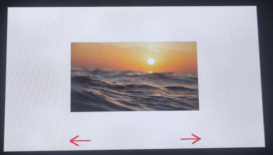
07_display_bmp
This example demonstrates how to read and display BMP images from a TF card.
Hardware Connection
- Connect the board to the computer using a USB cable
- Insert a TF card containing images into the ESP32-S3-Touch-LCD-4.3C.
Code
07_display_bmp.ino
/*
* Read BMP files from the TF card and display on the screen.
* Use the touchscreen to switch between images.
*/
#include "src/rgb_lcd_port/rgb_lcd_port.h"          // Header for Waveshare RGB LCD driver
#include "src/rgb_lcd_port/gui_paint/gui_paint.h"   // Header for graphical drawing functions
#include "src/gt911/gt911.h"           // Header for touch screen operations (GT911)
#include "src/rgb_lcd_port/gui_paint/gui_bmp.h"         // Header for BMP image handling
#include "src/user_sd/user_sd.h"           //

#define MAX_BMP_FILES 50  // Maximum number of BMP files supported
static char *BmpPath[MAX_BMP_FILES]; // Array to store full paths of BMP files
static uint8_t bmp_num; // Counter for the number of BMP files found

/**
 * Function to list all BMP files in a given directory.
 *
 * @param base_path The base directory to search for BMP files.
 */
void list_files(const char *base_path) {
    // Open the specified directory
    File dir = SD_MMC.open(base_path);
    if (!dir) {
        Serial.println("Failed to open directory!"); // Print an error if the directory can't be opened
        return;
    }

    // Check if the provided path is a valid directory
    if (!dir.isDirectory()) {
        Serial.println("Provided path is not a directory!"); // Print an error if the path isn't a directory
        dir.close();
        return;
    }

    int i = 0; // Initialize file counter
    static char mount_point[] = MOUNT_POINT; // Mount point for the TF card
    File file = dir.openNextFile(); // Open the first file in the directory

    // Iterate through the directory and process files
    while (file && i < MAX_BMP_FILES) {
        if (!file.isDirectory()) { // Skip directories
            const char *file_name = file.name(); // Get the name of the current file
            size_t len = strlen(file_name);

            // Check if the file extension is ".bmp" (case insensitive)
            if (len > 4 && strcasecmp(&file_name[len - 4], ".bmp") == 0) {
                size_t length = strlen(mount_point) + strlen(file_name) + 2; // Calculate memory needed for full path
                BmpPath[i] = (char *)malloc(length); // Allocate memory for the full path
                if (BmpPath[i]) {
                    // Combine mount point and file name into the full path
                    snprintf(BmpPath[i], length, "%s/%s", mount_point, file_name);
                    i++; // Increment the file counter
                }else{
                    Serial.println("Memory allocation failed for BMP path!"); // Print an error if memory allocation fails
                }
            }
        }
        file.close(); // Close the current file
        file = dir.openNextFile(); // Open the next file in the directory
    }

    bmp_num = i; // Set the number of BMP files found
    Serial.print("Found BMP files: ");
    Serial.println(bmp_num); // Print the number of BMP files found

    dir.close(); // Close the directory
}


void setup() {
  touch_gt911_point_t point_data;  // Structure to store touch point data

  Serial.begin(115200);
  DEV_I2C_Init();
  IO_EXTENSION_Init();
  // Initialize the GT911 touch screen controller
  touch_gt911_init(DEV_I2C_Get_Bus_Device());

  // Initialize the Waveshare ESP32-S3 RGB LCD
  waveshare_esp32_s3_rgb_lcd_init();
  // Turn on the LCD backlight
  wavesahre_rgb_lcd_bl_on();
  // EXAMPLE_PIN_NUM_TOUCH_INT
    // Allocate memory for the LCD's frame buffer
    UDOUBLE Imagesize = EXAMPLE_LCD_H_RES * EXAMPLE_LCD_V_RES * 2; // Each pixel uses 2 bytes in RGB565 format
    UBYTE *BlackImage;
    if ((BlackImage = (UBYTE *)malloc(Imagesize)) == NULL) // Check if memory allocation is successful
    {
        printf("Failed to allocate memory for frame buffer...\r\n");
        exit(0); // Exit if memory allocation fails
    }

    // Initialize the graphics canvas with the allocated buffer
    Paint_NewImage(BlackImage, EXAMPLE_LCD_H_RES, EXAMPLE_LCD_V_RES, 0, WHITE);

    // Set the scale for the graphical canvas
    Paint_SetScale(65);

    // Clear the canvas and fill it with a white background
    Paint_Clear(WHITE);

    // Initialize TF card
    if (sd_mmc_init() == ESP_OK)
    {
        Paint_DrawString_EN(200, 200, "TF Card OK!", &Font24, BLACK, WHITE); // Display TF card success message
        Paint_DrawString_EN(200, 240, "Click the arrow to start.", &Font24, BLACK, WHITE); // Display prompt

        // Draw navigation arrows
        Paint_DrawLine(540, 450, 600, 450, RED, DOT_PIXEL_2X2, LINE_STYLE_SOLID);
        Paint_DrawLine(575, 435, 600, 450, RED, DOT_PIXEL_2X2, LINE_STYLE_SOLID); // Right arrow
        Paint_DrawLine(575, 465, 600, 450, RED, DOT_PIXEL_2X2, LINE_STYLE_SOLID);

        // List BMP files from the TF card
        list_files("/");
        if (bmp_num == 0)
        {
            Paint_DrawString_EN(200, 280, "There is no BMP file in the memory card.", &Font24, RED, WHITE); // Display prompt
            wavesahre_rgb_lcd_display(BlackImage);
            return;
        }
        else
        {
            // Draw navigation arrows
            Paint_DrawLine(540, 450, 600, 450, RED, DOT_PIXEL_2X2, LINE_STYLE_SOLID);
            Paint_DrawLine(575, 435, 600, 450, RED, DOT_PIXEL_2X2, LINE_STYLE_SOLID); // Right arrow
            Paint_DrawLine(575, 465, 600, 450, RED, DOT_PIXEL_2X2, LINE_STYLE_SOLID);

            // Display the initial image on the screen
            wavesahre_rgb_lcd_display(BlackImage);
        }
    }
    else
    {
        // If TF card initialization fails
        Paint_DrawString_EN(200, 200, "TF Card Fail!", &Font24, BLACK, WHITE);
        wavesahre_rgb_lcd_display(BlackImage);
        return;

    }

    // Initial touch point variables
    int8_t i = 0;
    static uint16_t prev_x;
    static uint16_t prev_y;

    while (1)
    {
        point_data = touch_gt911_read_point(1);  // Read touch data
        if (point_data.cnt == 1)  // Check if touch is detected
        {
            // If touch position hasn't changed, continue the loop
            if ((prev_x == point_data.x[0]) && (prev_y == point_data.y[0]))
            {
                continue;
            }

            // If touch is within the left navigation area, switch to the previous image
            if (point_data.x[0] > 200 && point_data.x[0] < 260 && point_data.y[0] > 420 && point_data.y[0] < 480)
            {
                i--;
                if (i < 0)  // If index goes below 0, wrap around to the last image
                {
                    i = bmp_num - 1;
                }
                Paint_Clear(WHITE);  // Clear the screen
                GUI_ReadBmp(200, 123, BmpPath[i]);  // Read and display the previous BMP image

                // Draw navigation arrows
                Paint_DrawLine(200, 450, 260, 450, RED, DOT_PIXEL_2X2, LINE_STYLE_SOLID); // Left arrow
                Paint_DrawLine(200, 450, 225, 435, RED, DOT_PIXEL_2X2, LINE_STYLE_SOLID);
                Paint_DrawLine(200, 450, 225, 465, RED, DOT_PIXEL_2X2, LINE_STYLE_SOLID);

                // Right arrow
                Paint_DrawLine(540, 450, 600, 450, RED, DOT_PIXEL_2X2, LINE_STYLE_SOLID);
                Paint_DrawLine(575, 435, 600, 450, RED, DOT_PIXEL_2X2, LINE_STYLE_SOLID);
                Paint_DrawLine(575, 465, 600, 450, RED, DOT_PIXEL_2X2, LINE_STYLE_SOLID);

                wavesahre_rgb_lcd_display(BlackImage);  // Update display

                prev_x = point_data.x[0];  // Update previous touch position
                prev_y = point_data.y[0];
            }
            // If touch is within the right navigation area, switch to the next image
            else if (point_data.x[0] > 540 && point_data.x[0] < 600 && point_data.y[0] > 420 && point_data.y[0] < 480)
            {
                i++;
                if (i > bmp_num - 1)  // If index exceeds the number of images, wrap around to the first image
                {
                    i = 0;
                }
                Paint_Clear(WHITE);  // Clear the screen
                GUI_ReadBmp(200, 123, BmpPath[i]);  // Read and display the next BMP image

                // Draw navigation arrows
                Paint_DrawLine(200, 450, 260, 450, RED, DOT_PIXEL_2X2, LINE_STYLE_SOLID); // Left arrow
                Paint_DrawLine(200, 450, 225, 435, RED, DOT_PIXEL_2X2, LINE_STYLE_SOLID);
                Paint_DrawLine(200, 450, 225, 465, RED, DOT_PIXEL_2X2, LINE_STYLE_SOLID);

                // Right arrow
                Paint_DrawLine(540, 450, 600, 450, RED, DOT_PIXEL_2X2, LINE_STYLE_SOLID);
                Paint_DrawLine(575, 435, 600, 450, RED, DOT_PIXEL_2X2, LINE_STYLE_SOLID);
                Paint_DrawLine(575, 465, 600, 450, RED, DOT_PIXEL_2X2, LINE_STYLE_SOLID);

                wavesahre_rgb_lcd_display(BlackImage);  // Update display

                prev_x = point_data.x[0];  // Update previous touch position
                prev_y = point_data.y[0];
            }
        }
        delay(30);  // Delay for 30ms to avoid high CPU usage
    }
}

void loop() {
  // put your main code here, to run repeatedly:

}
Code Analysis
-
setup():- Initializes all hardware and communication interfaces, mounts the TF card, scans for BMP file paths, and contains an infinite loop for continuously reading touch operations and switching between displaying image files from the TF card.
-
list_files(const char *base_path):- Traverses the root directory of the TF card, finds all
.bmpfiles, and stores their full paths.
- Traverses the root directory of the TF card, finds all
-
sd_mmc_init():- Mounts the TF card file system.
-
touch_gt911_init():- Initializes the GT911 touchscreen controller.
-
GUI_ReadBmp():- Reads the specified BMP file from the TF card and draws it into the frame buffer.
Operation Result
-
After successful flashing, tapping the left/right navigation arrow areas switches the display to the previous or next BMP image and updates the navigation arrow graphics.
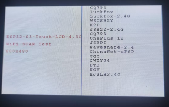
08_wifi_scan
This example demonstrates displaying the names of scanned Wi-Fi networks on the screen (Chinese SSIDs cannot be displayed).
Hardware Connection
- Connect the board to the computer using a USB cable
Code
08_wifi_scan.ino
/*
* This example scans for nearby Wi-Fi signals and displays the
* Wi-Fi names (SSIDs) on the right side of the LCD screen.
*/
#include "src/rgb_lcd_port/rgb_lcd_port.h"          // Header for Waveshare RGB LCD driver
#include "src/rgb_lcd_port/gui_paint/gui_paint.h"   // Header for graphical drawing functions
#include "src/user_wifi/user_wifi.h"       // Header for Wi-Fi initialization and scanning functions

#define ROTATE ROTATE_0  // Set screen rotation: options are 0, 90, 180, 270 degrees

void setup() {
    Serial.begin(115200);  // Initialize the serial port for debugging

    // Check if PSRAM is available and functional
    if (psramFound()) {
        Serial.println("PSRAM is enabled and found!");
    }else{
        Serial.println("PSRAM not found or not enabled.");
    }
    delay(100);  // Short delay to allow initialization processes

    // Initialize Wi-Fi functionality
    wifi_scan_init();

    // Initialize I2C and the IO EXTENSION GPIO hardware interface
    DEV_I2C_Init();  // Start I2C communication
    IO_EXTENSION_Init();   // Configure the IO EXTENSION GPIO control chip

    // Initialize the RGB LCD display
    waveshare_esp32_s3_rgb_lcd_init();

    // Turn on the LCD backlight for visibility
    wavesahre_rgb_lcd_bl_on();
    // Uncomment the next line to turn off the backlight if needed
    // wavesahre_rgb_lcd_bl_off();

    // Allocate memory for the framebuffer (image buffer) in PSRAM
    UDOUBLE Imagesize = EXAMPLE_LCD_H_RES * EXAMPLE_LCD_V_RES * 2;  // Each pixel takes 2 bytes in RGB565 format
    UBYTE *BlackImage;
    if ((BlackImage = (UBYTE *)heap_caps_malloc(Imagesize, MALLOC_CAP_SPIRAM)) == NULL) {
        Serial.println("Failed to allocate memory for the framebuffer.");
        exit(0); // Exit the program if memory allocation fails
    }

    // Initialize a new image canvas and set its background color
    Paint_NewImage(BlackImage, EXAMPLE_LCD_H_RES, EXAMPLE_LCD_V_RES, 0, WHITE);

    // Configure the canvas properties (scale and rotation)
    Paint_SetScale(65);       // Set the image scale
    Paint_SetRotate(ROTATE);  // Set the rotation angle (default 0 degrees)
    Paint_Clear(WHITE);       // Clear the canvas and fill it with a white background

    // Counter for Wi-Fi networks with Chinese SSIDs
    uint8_t chinese_num = 0;

    // Display static information on the screen
    Paint_DrawString_EN(10, 160, "ESP32-S3-Touch-LCD-4.3C", &Font24, RED, WHITE);  // Display title
    Paint_DrawString_EN(10, 200, "WiFi SCAN Test", &Font24, RED, WHITE);       // Display Wi-Fi scan test message
    Paint_DrawString_EN(10, 240, "800x480", &Font24, RED, WHITE);              // Display resolution
    Paint_DrawLine(400, 0, 400, 480, BLUE, DOT_PIXEL_2X2, LINE_STYLE_SOLID);   // Draw a vertical separator line
    Paint_DrawString_EN(440, 0, "Scanning now...", &Font24, BLACK, WHITE);     // Display scanning status
    wavesahre_rgb_lcd_display(BlackImage);  // Refresh the display to show the initial static messages

    // Clear the scanning message area
    Paint_ClearWindows(440, 0, 800, 25, WHITE);

    // Start Wi-Fi scanning and display the results
    wifi_scan();

    // Update the display with the new Wi-Fi scan results
    wavesahre_rgb_lcd_display(BlackImage);
}

void loop() {
    // Main loop remains empty for now
    // You can add additional functionality or updates to run continuously here
}
Code Analysis
-
setup():- Responsible for initializing all communication interfaces and LCD/Wi-Fi hardware. - Prepares the graphics environment, allocates memory for the buffer. Draws the static UI and performs a single Wi-Fi scan (wifi_scan), directly displaying the list of all found network SSIDs in the right area of the LCD screen.
-
wifi_scan_init():- Initializes the Wi-Fi hardware and configuration.
-
wifi_scan():- Performs the actual Wi-Fi scan and directly draws the results onto the LCD screen.
Operation Result
-
After successful flashing, the scanned Wi-Fi names are displayed on the screen.
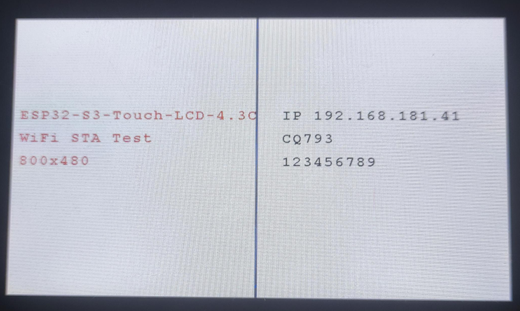
09_wifi_sta
This example demonstrates using the screen to display the IP information after connecting to a hotspot.
Hardware Connection
- Connect the board to the computer using a USB cable
Code
09_wifi_sta.ino
/*
* This example connects to an AP. Once connected, it displays
* the IP address, Wi-Fi name, and password. If the connection
* fails, it shows a connection failure message.
*/
#include "src/rgb_lcd_port/rgb_lcd_port.h"              // Header for Waveshare RGB LCD driver
#include "src/rgb_lcd_port/gui_paint/gui_paint.h"   // Header for graphical drawing functions
#include "src/user_wifi/user_wifi.h"       // Header for Wi-Fi initialization and scanning functions

#define USER_SSID "SSID"  // Wi-Fi SSID (network name)
#define USER_PASS "PASSWORD"  // Wi-Fi password

void setup() {
    Serial.begin(115200);  // Initialize the serial port for debugging

    // Check if PSRAM is available and functional
    if (psramFound()) {
        Serial.println("PSRAM is enabled and found!");
    }else{
        Serial.println("PSRAM not found or not enabled.");
    }
    delay(100);  // Short delay to allow initialization processes

    // Initialize I2C and the IO EXTENSION GPIO hardware interface
    DEV_I2C_Init();  // Start I2C communication
    IO_EXTENSION_Init();   // Configure the IO EXTENSION GPIO control chip

    // Initialize the RGB LCD display
    waveshare_esp32_s3_rgb_lcd_init();

    // Turn on the LCD backlight for visibility
    wavesahre_rgb_lcd_bl_on();
    // Uncomment the next line to turn off the backlight if needed
    // wavesahre_rgb_lcd_bl_off();

    // Allocate memory for the framebuffer (image buffer) in PSRAM
    UDOUBLE Imagesize = EXAMPLE_LCD_H_RES * EXAMPLE_LCD_V_RES * 2;  // Each pixel takes 2 bytes in RGB565 format
    UBYTE *BlackImage;
    if ((BlackImage = (UBYTE *)heap_caps_malloc(Imagesize, MALLOC_CAP_SPIRAM)) == NULL) {
        Serial.println("Failed to allocate memory for the framebuffer.");
        exit(0); // Exit the program if memory allocation fails
    }

    // Initialize a new image canvas and set its background color
    Paint_NewImage(BlackImage, EXAMPLE_LCD_H_RES, EXAMPLE_LCD_V_RES, 0, WHITE);

    // Configure the canvas properties (scale and rotation)
    Paint_SetScale(65);       // Set the image scale
    Paint_Clear(WHITE);       // Clear the canvas and fill it with a white background

    // Display static information on the screen
    Paint_DrawString_EN(10, 160, "ESP32-S3-Touch-LCD-4.3C", &Font24, RED, WHITE);  // Display title
    Paint_DrawString_EN(10, 200, "WiFi STA Test", &Font24, RED, WHITE);       // Display Wi-Fi scan test message
    Paint_DrawString_EN(10, 240, "800x480", &Font24, RED, WHITE);              // Display resolution
    Paint_DrawLine(400, 0, 400, 480, BLUE, DOT_PIXEL_2X2, LINE_STYLE_SOLID);   // Draw a vertical separator line
    Paint_DrawString_EN(440, 160, "wifi connecting......", &Font24, BLACK, WHITE);     // Display scanning status
    wavesahre_rgb_lcd_display(BlackImage);  // Refresh the display to show the initial static messages

    // Clear the scanning message area
    Paint_ClearWindows(440, 160, 800, 185, WHITE);

    // Initialize Wi-Fi functionality and attempt to connect to the provided network
    wifi_sta_init(USER_SSID, USER_PASS);

    // Update the display with the new Wi-Fi scan results
    wavesahre_rgb_lcd_display(BlackImage);
}

void loop() {
    // Main loop remains empty for now
    // You can add additional functionality or updates to run continuously here
}
Code Analysis
-
setup():- Initializes all communication interfaces and LCD hardware, and checks the PSRAM status.
- Allocates the frame buffer, initializes the drawing canvas, and draws the static UI (title, separator line, and "Connecting..." prompt).
- Calls wifi_sta_init(USER_SSID, USER_PASS) to attempt connection to a predefined wireless access point.
-
wifi_sta_init(USER_SSID, USER_PASS):- Initializes the Wi-Fi module and attempts to connect to the specified SSID and password in Station (STA) mode. A side effect is updating the connection status on the LCD.
Operation Result
-
After successful flashing, the right side of the screen updates to display the IP address, Wi-Fi name, etc., or a connection failure message after a successful or failed connection.
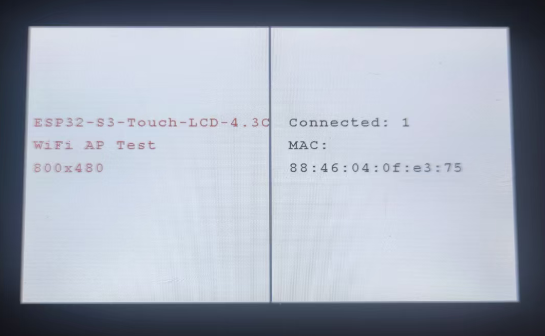
10_wifi_ap
This example demonstrates using the screen to display the status of a hotspot, showing the MAC addresses of connected devices.
Hardware Connection
- Connect the board to the computer using a USB cable
Code
10_wifi_ap.ino
/*
* Create an Access Point (AP), and when devices connect,
* display their MAC addresses on the screen.
*/
#include "src/rgb_lcd_port/rgb_lcd_port.h"              // Header for Waveshare RGB LCD driver
#include "src/rgb_lcd_port/gui_paint/gui_paint.h"   // Header for graphical drawing functions
#include "src/user_wifi/user_wifi.h"       // Header for Wi-Fi initialization and scanning functions

#define USER_SSID "ESP32-S3-Touch-LCD-4.3C"  // Wi-Fi SSID (network name)
#define USER_PASS "66668888"  // Wi-Fi password

void setup() {
    Serial.begin(115200);  // Initialize the serial port for debugging

    // Check if PSRAM is available and functional
    if (psramFound()) {
        Serial.println("PSRAM is enabled and found!");
    }else{
        Serial.println("PSRAM not found or not enabled.");
    }
    delay(100);  // Short delay to allow initialization processes

    // Initialize I2C and the IO EXTENSION GPIO hardware interface
    DEV_I2C_Init();  // Start I2C communication
    IO_EXTENSION_Init();   // Configure the IO EXTENSION GPIO control chip

    // Initialize the RGB LCD display
    waveshare_esp32_s3_rgb_lcd_init();

    // Turn on the LCD backlight for visibility
    wavesahre_rgb_lcd_bl_on();
    // Uncomment the next line to turn off the backlight if needed
    // wavesahre_rgb_lcd_bl_off();

    // Allocate memory for the framebuffer (image buffer) in PSRAM
    UDOUBLE Imagesize = EXAMPLE_LCD_H_RES * EXAMPLE_LCD_V_RES * 2;  // Each pixel takes 2 bytes in RGB565 format
    UBYTE *BlackImage;
    if ((BlackImage = (UBYTE *)heap_caps_malloc(Imagesize, MALLOC_CAP_SPIRAM)) == NULL) {
        Serial.println("Failed to allocate memory for the framebuffer.");
        exit(0); // Exit the program if memory allocation fails
    }

    // Initialize a new image canvas and set its background color
    Paint_NewImage(BlackImage, EXAMPLE_LCD_H_RES, EXAMPLE_LCD_V_RES, 0, WHITE);

    // Configure the canvas properties (scale and rotation)
    Paint_SetScale(65);       // Set the image scale
    Paint_Clear(WHITE);       // Clear the canvas and fill it with a white background

    // Display static information on the screen
    Paint_DrawString_EN(10, 160, "ESP32-S3-Touch-LCD-4.3C", &Font24, RED, WHITE);  // Display title
    Paint_DrawString_EN(10, 200, "WiFi AP Test", &Font24, RED, WHITE);       // Display Wi-Fi scan test message
    Paint_DrawString_EN(10, 240, "800x480", &Font24, RED, WHITE);              // Display resolution
    Paint_DrawLine(400, 0, 400, 480, BLUE, DOT_PIXEL_2X2, LINE_STYLE_SOLID);   // Draw a vertical separator line
    Paint_DrawString_EN(430, 160, "Connected: 0", &Font24, BLACK, WHITE);        // Display initial connection status
    wavesahre_rgb_lcd_display(BlackImage);  // Refresh the display to show the initial static messages

    // Initialize Wi-Fi functionality and attempt to connect to the provided network
    wifi_ap_init(USER_SSID, USER_PASS);

    // Update the display with the new Wi-Fi scan results
    wavesahre_rgb_lcd_display(BlackImage);
    static uint8_t connection_num = 0;
    while (1)
    {
      char mac[32];
      uint8_t n = wifi_ap_StationNum();
      if (connection_num != n)
      {
        char station_num[32];
        char station_mac[MAC_Addr_length];

        Paint_ClearWindows(430, 160, 800, 480, WHITE);  // Clear the section of the screen displaying the connection info
        snprintf(station_num, sizeof(station_num), "Connected: %d", n); // Format the number of connected stations
        Paint_DrawString_EN(430, 160, station_num, &Font24, BLACK, WHITE);  // Display the number of connected devices

        if (n == 0)
        {
            Serial.println("No device connected.");  // Log error if no devices are connected
        }
        else
        {
            Paint_DrawString_EN(430, 200 , "MAC:", &Font24, BLACK, WHITE);  // Label for MAC address
            for (int i = 0; i < n; i++) {
              wifi_ap_StationMac(station_mac, i);
              Paint_DrawString_EN(430, 240 + (i * 40), station_mac, &Font24, BLACK, WHITE);  // Display MAC address
              Serial.print("MAC Address: ");
              Serial.println(station_mac);
            }
            Serial.println("");
        }
        // Update the display with the new Wi-Fi scan results
        wavesahre_rgb_lcd_display(BlackImage);
        connection_num = n;
      }
      delay(100);
    }
}

void loop() {
    // Main loop remains empty for now
    // You can add additional functionality or updates to run continuously here

}
Code Analysis
-
setup():- Initializes all hardware and the graphics environment, and configures the device as a Wireless Access Point (AP), broadcasting a network with preset SSID and password.
- This function contains an infinite loop: it continuously checks the number of devices connected to the AP. Upon detecting a device connection or disconnection, it clears the status area on the screen and updates the display to show the current connection count and a list of MAC addresses for each connected device.
wifi_ap_init(USER_SSID, USER_PASS):
-
Initializes the Wi-Fi module and configures it into Access Point (AP) mode using the specified network name and password.
-
wifi_ap_StationNum():- Dynamically updates the right side of the LCD screen to show the number of connected devices.
-
wifi_ap_StationMac(station_mac, i):- Displays the MAC address of each connected device.
Operation Result
-
After successful flashing, the Wi-Fi connection count and MAC addresses of devices are displayed.
11_speaker_microphone
This example demonstrates implementing recording and playback functionality via the touchscreen.
Hardware Connection
- Connect the board to the computer using a USB cable
Code
11_speaker_microphone.ino
/*
* Performs a five-point touch test and demonstrates basic usage of double buffering.
*/
#include "src/rgb_lcd_port/rgb_lcd_port.h"              // Header for Waveshare RGB LCD driver
#include "src/rgb_lcd_port/gui_paint/gui_paint.h"   // Header for graphical drawing functions
#include "src/gt911/gt911.h"           // Header for touch screen operations (GT911)
#include "src/user_sd/user_sd.h"           // TF card (not used directly here)
#include "src/speaker_microphone/codec_dev.h"    // Codec driver
#include "esp_check.h"    // Error handling macros

// Configuration macros
#define RECORD_TIME_SEC 5
#define BUFFER_SIZE (CODEC_DEFAULT_SAMPLE_RATE * RECORD_TIME_SEC * CODEC_DEFAULT_CHANNEL * (CODEC_DEFAULT_BIT_WIDTH / 8))

static int16_t *record_buffer = NULL;
UBYTE *BlackImage;

// Function to handle recording and playback
void play_or_pause(bool play)
{
    if (play)
    {
        // Recording logic
        Paint_DrawLine(390, 435, 390, 465, RED, DOT_PIXEL_2X2, LINE_STYLE_SOLID);
        Paint_DrawLine(410, 435, 410, 465, RED, DOT_PIXEL_2X2, LINE_STYLE_SOLID);
        Paint_DrawString_EN(200, 150, "Start recording...", &Font48, BLACK, WHITE);
        wavesahre_rgb_lcd_display(BlackImage);

        size_t total_bytes = 0;
        while (total_bytes < BUFFER_SIZE)
        {
            size_t bytes_read = 0;
            mic_i2s_read(record_buffer + total_bytes / 2,
                         BUFFER_SIZE - total_bytes,
                         &bytes_read, portMAX_DELAY);
            total_bytes += bytes_read;
        }

        Paint_Clear(WHITE);
        Paint_DrawLine(420, 450, 390, 435, RED, DOT_PIXEL_2X2, LINE_STYLE_SOLID);
        Paint_DrawLine(420, 450, 390, 465, RED, DOT_PIXEL_2X2, LINE_STYLE_SOLID);
        Paint_DrawLine(390, 435, 390, 465, RED, DOT_PIXEL_2X2, LINE_STYLE_SOLID);
        Paint_DrawString_EN(250, 150, "Recording done.", &Font48, BLACK, WHITE);
        wavesahre_rgb_lcd_display(BlackImage);
    }
    else
    {
        // Playback logic
        Paint_DrawLine(390, 435, 390, 465, RED, DOT_PIXEL_2X2, LINE_STYLE_SOLID);
        Paint_DrawLine(410, 435, 410, 465, RED, DOT_PIXEL_2X2, LINE_STYLE_SOLID);
        Paint_DrawString_EN(200, 150, "Start playing...", &Font48, BLACK, WHITE);
        wavesahre_rgb_lcd_display(BlackImage);

        size_t total_bytes = 0;
        while (total_bytes < BUFFER_SIZE)
        {
            size_t bytes_written = 0;
            speaker_i2s_write(record_buffer + total_bytes / 2,
                              BUFFER_SIZE - total_bytes,
                              &bytes_written, portMAX_DELAY);
            total_bytes += bytes_written;
        }

        Paint_Clear(WHITE);
        Paint_DrawLine(420, 450, 390, 435, RED, DOT_PIXEL_2X2, LINE_STYLE_SOLID);
        Paint_DrawLine(420, 450, 390, 465, RED, DOT_PIXEL_2X2, LINE_STYLE_SOLID);
        Paint_DrawLine(390, 435, 390, 465, RED, DOT_PIXEL_2X2, LINE_STYLE_SOLID);
        Paint_DrawString_EN(250, 150, "Playback done.", &Font48, BLACK, WHITE);
        wavesahre_rgb_lcd_display(BlackImage);
    }
}

void setup() {
    touch_gt911_point_t point_data;  // Structure to store touch point data

    Serial.begin(115200);
    DEV_I2C_Init();
    IO_EXTENSION_Init();
    // Initialize the GT911 touch screen controller
    touch_gt911_init(DEV_I2C_Get_Bus_Device());

    // Initialize the Waveshare ESP32-S3 RGB LCD
    waveshare_esp32_s3_rgb_lcd_init();
    // Turn on the LCD backlight
    wavesahre_rgb_lcd_bl_on();

    // Allocate LCD frame buffer
    UDOUBLE Imagesize = EXAMPLE_LCD_H_RES * EXAMPLE_LCD_V_RES * 2;
    BlackImage = (UBYTE *)malloc(Imagesize);
    if (!BlackImage)
    {
        Serial.println("Failed to allocate memory for frame buffer...");
        exit(0);
    }

    // Initialize the graphics canvas with buf2
    Paint_NewImage(BlackImage, EXAMPLE_LCD_H_RES, EXAMPLE_LCD_V_RES, 0, WHITE);

    // Set the scale for the graphical canvas
    Paint_SetScale(65);

    // Clear the canvas and fill it with a white background
    Paint_Clear(WHITE);

    // Draw initial red record button
    Paint_DrawCircle(405, 450, 15, RED, DOT_PIXEL_2X2, DRAW_FILL_FULL);
    Paint_DrawString_EN(100, 150, "Click to start recording", &Font48, BLACK, WHITE);
    wavesahre_rgb_lcd_display(BlackImage);

    // Initialize speaker codec
    codec_init();
    speaker_codec_volume_set(100, NULL);
    microphone_codec_gain_set(30, NULL);

    // Allocate memory for recording buffer
    record_buffer = (int16_t *)heap_caps_malloc(BUFFER_SIZE * sizeof(int16_t), MALLOC_CAP_SPIRAM | MALLOC_CAP_8BIT);
    if (!record_buffer)
    {
        Serial.println("Failed to allocate buffer");
        vTaskDelete(NULL);
        return;
    }

    // Touch handling loop
    static uint16_t prev_x;
    static uint16_t prev_y;
    bool is_playing = false;

    // Main application loop
    while (1)
    {
        point_data = touch_gt911_read_point(1);
        if (point_data.cnt == 1)
        {
            if (prev_x == point_data.x[0] && prev_y == point_data.y[0])
            {
                continue;
            }
            else if (point_data.x[0] > 390 && point_data.x[0] < 420 &&
                     point_data.y[0] > 420 && point_data.y[0] < 480)
            {
                Paint_Clear(WHITE);
                is_playing = !is_playing;
                play_or_pause(is_playing);

                prev_x = point_data.x[0];
                prev_y = point_data.y[0];
            }
        }
        delay(30);
    }
}

void loop() {
  // put your main code here, to run repeatedly:

}
Code Analysis
-
setup():- This function initializes all hardware, the touchscreen, LCD, and audio codec, allocates audio buffers, then enters an infinite loop that continuously monitors touch operations to switch between recording and playing back a 5-second audio clip.
-
play_or_pause(bool play):- Toggles the program state based on the boolean parameter: if true, it reads 5 seconds of audio data from the microphone and stores it in a buffer (recording); if false, it reads data from the buffer and outputs it to the speaker (playback), updating the status and icon on the screen.
-
codec_init():- Initializes the audio codec (codec_init), sets speaker volume and microphone gain, and configures the audio path.
-
mic_i2s_read() / speaker_i2s_write():- Called inside the play_or_pause function, used for reading audio data from the microphone and writing audio data to the speaker, respectively.
Operation Result
-
After successful flashing, tapping the designated area switches between recording and playback operations, enabling both functions.
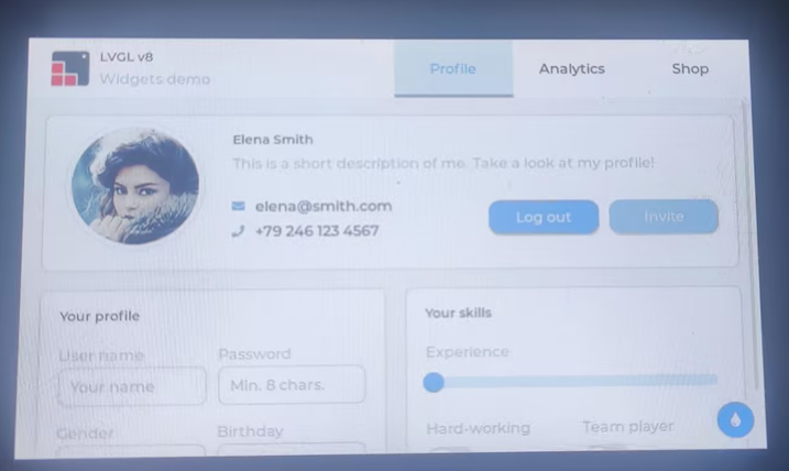
12_lvgl_transplant
This example demonstrates the porting of LVGL.
Hardware Connection
- Connect the board to the computer using a USB cable
Code
12_lvgl_transplant.ino
/*
* Ported LVGL 8.4 and display the official demo interface.
*/
#include "src/lvgl_port/lvgl_port.h"       // LVGL porting functions for integration
#include <demos/lv_demos.h>        // LVGL demo headers

void setup() {
    static esp_lcd_panel_handle_t panel_handle = NULL; // Declare a handle for the LCD panel
    static esp_lcd_touch_handle_t tp_handle = NULL;    // Declare a handle for the touch panel

    DEV_I2C_Init();
    IO_EXTENSION_Init();
    // Initialize the GT911 touch screen controller
    tp_handle = touch_gt911_init(DEV_I2C_Get_Bus_Device());

    // Initialize the Waveshare ESP32-S3 RGB LCD hardware
    panel_handle = waveshare_esp32_s3_rgb_lcd_init();

    // Turn on the LCD backlight
    wavesahre_rgb_lcd_bl_on();

    // Initialize LVGL with the panel and touch handles
    ESP_ERROR_CHECK(lvgl_port_init(panel_handle, tp_handle));

    Serial.println("Display LVGL demos");

    // Lock the mutex because LVGL APIs are not thread-safe
    if (lvgl_port_lock(-1)) {
        // Uncomment and run the desired demo functions here
        // lv_demo_stress();  // Stress test demo
        // lv_demo_benchmark(); // Benchmark demo
        // lv_demo_music();     // Music demo
        lv_demo_widgets();    // Widgets demo

        // Release the mutex after the demo execution
        lvgl_port_unlock();
    }
}

void loop() {
  // put your main code here, to run repeatedly:

}
Code Analysis
-
setup():- It initializes all hardware (I2C bus, I/O expansion chip) and the GT911 touchscreen, then initializes the Waveshare RGB LCD screen and turns on the backlight. Core functionality: It integrates the LCD and touchscreen handles into the LVGL graphics library (lvgl_port_init), locks the LVGL mutex, and then launches the official LVGL Widgets demo interface (lv_demo_widgets).
-
lv_demo_widgets():- Starts the LVGL demo: loads and runs the official LVGL-provided Widgets example interface.
Operation Result
-
After successful flashing, the LVGL sample program is displayed.
Other Notes
- If screen drift occurs during use, please refer to the official ESP FAQ.
- The version of LVGL used is 8.4.0. You can refer to and use the LVGL API via the following documentation:
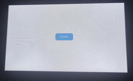
13_lvgl_btn
Hardware Connection
- Connect the board to the computer using a USB cable
Code
13_lvgl_btn.ino
/*
* Creating a button using LVGL.
*/

#include "src/lvgl_port/lvgl_port.h"       // LVGL porting functions for integration
#include <demos/lv_demos.h>        // LVGL demo headers

static const char *TAG = "main";
/**
 * @brief  Event callback for button interactions
 * @param  *e: A pointer to `lv_event_t` containing event-related data
 * @return None
 */
static void btn_event_cb(lv_event_t * e)
{
    lv_event_code_t code = lv_event_get_code(e); // Retrieve the event code
    if (code == LV_EVENT_CLICKED) {
        Serial.println("Button Pressed.");
    }
}

/**
 * @brief  Creating a button using LVGL
 * @return None
 */
void lvgl_btn()
{
    // Create a button on the active screen
    lv_obj_t * btn = lv_btn_create(lv_scr_act());
    lv_obj_set_pos(btn, 10, 10);                      // Set the button's position
    lv_obj_set_size(btn, 120, 50);                    // Set the button's size
    lv_obj_align(btn, LV_ALIGN_CENTER, 0, 0);         // Align the button to the center of the screen

    // Add the event callback to handle button actions
    lv_obj_add_event_cb(btn, btn_event_cb, LV_EVENT_ALL, NULL);

    // Create a label and add it to the button
    lv_obj_t * label = lv_label_create(btn);
    lv_label_set_text(label, "Button");               // Set the label's text
    lv_obj_center(label);                             // Center the label within the button
}

void setup() {
    static esp_lcd_panel_handle_t panel_handle = NULL; // Declare a handle for the LCD panel
    static esp_lcd_touch_handle_t tp_handle = NULL;    // Declare a handle for the touch panel

    Serial.begin(115200);
    DEV_I2C_Init();
    IO_EXTENSION_Init();

    // Initialize the GT911 touch screen controller
    tp_handle = touch_gt911_init(DEV_I2C_Get_Bus_Device());

    // Initialize the Waveshare ESP32-S3 RGB LCD hardware
    panel_handle = waveshare_esp32_s3_rgb_lcd_init();

    // Turn on the LCD backlight
    wavesahre_rgb_lcd_bl_on();

    // Initialize LVGL with the panel and touch handles
    ESP_ERROR_CHECK(lvgl_port_init(panel_handle, tp_handle));

    Serial.println("Display LVGL demos");

    // Lock the mutex because LVGL APIs are not thread-safe
    if (lvgl_port_lock(-1)) {
         lvgl_btn();
        // Release the mutex after the demo execution
        lvgl_port_unlock();
    }
}

void loop() {
  // put your main code here, to run repeatedly:

}
Code Analysis
-
setup():- Initializes all hardware (serial port, I2C bus, I/O expansion, GT911 touchscreen) and the Waveshare RGB LCD screen. Core functionality: It integrates the LCD and touchscreen drivers into the LVGL graphics library (lvgl_port_init), then locks the LVGL mutex and calls lvgl_btn() to create and display an interactive button on the screen.
-
lvgl_btn():- Creates a button object at the center of the LVGL's current active screen. Sets the button's size, position, and label text ("Button"). Binds the btn_event_cb callback function to the button to respond to user interaction.
-
btn_event_cb(lv_event_t * e):- Triggered when the button is clicked (LV_EVENT_CLICKED). Prints the message "Button Pressed." to the serial port.
Operation Result
-
After successful flashing, a button will be displayed in the center of the screen. Open the Serial Monitor, and when interacting with the button, the monitor will output "Button Pressed.”.
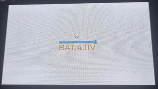
14_lvgl_slider
Hardware Connection
- Connect the board to the computer using a USB cable
Code
14_lvgl_slider.ino
/*
 * Demonstrates an LVGL slider to control LED brightness and display battery voltage.
 */

#include "src/lvgl_port/lvgl_port.h"       // LVGL porting functions for integration
#include <demos/lv_demos.h>      // Optional: LVGL demo headers for extra examples

static lv_obj_t *label;          // Label to display slider value
static lv_obj_t *BAT_Label;      // Label to display battery voltage
char bat_v[20];                  // Buffer to store formatted battery voltage string

/**
 * @brief Callback function to update the battery voltage label.
 *
 * Called by an LVGL timer to refresh the battery voltage shown on the UI.
 *
 * @param timer Pointer to the LVGL timer object
 */
static void bat_cb(lv_timer_t * timer)
{
    lv_label_set_text(BAT_Label, bat_v); // Update the battery voltage label with latest value
}

/**
 * @brief Event callback for slider interaction.
 *
 * Triggered when the slider value changes.
 * Updates the label with the current value and adjusts LED brightness via PWM.
 *
 * @param e Pointer to the LVGL event descriptor
 */
static void slider_event_cb(lv_event_t * e)
{
    lv_obj_t *slider = lv_event_get_target(e); // Get the slider that triggered the event

    // Update the label with the slider's current value
    lv_label_set_text_fmt(label, "%" LV_PRId32, lv_slider_get_value(slider));

    // Set the PWM duty cycle based on slider value (inverted: 100 = off, 0 = full brightness)
    uint8_t duty = (100 - lv_slider_get_value(slider));
    IO_EXTENSION_Pwm_Output(duty); // Optional external PWM controller
}

/**
 * @brief Creates an LVGL slider to control LED brightness.
 *
 * Also creates a label to display slider value and another label to show battery voltage.
 */
void lvgl_slider(void)
{
    IO_EXTENSION_Pwm_Output(0); // Optional external control for brightness

    // Create the slider widget on the active LVGL screen
    lv_obj_t *slider = lv_slider_create(lv_scr_act());

    // Set slider dimensions and center it on screen
    lv_obj_set_width(slider, 200);
    lv_obj_center(slider);

    // Set initial slider value to 100 (LED off if active-low)
    lv_slider_set_value(slider, 100, LV_ANIM_OFF);

    // Attach the event callback for slider changes
    lv_obj_add_event_cb(slider, slider_event_cb, LV_EVENT_VALUE_CHANGED, NULL);

    // Create a label to display the current slider value
    label = lv_label_create(lv_scr_act());
    lv_label_set_text(label, "100"); // Initial label value
    lv_obj_align_to(label, slider, LV_ALIGN_OUT_TOP_MID, 0, -15); // Position above slider

    // Create a label for displaying battery voltage
    BAT_Label = lv_label_create(lv_scr_act());
    lv_obj_set_width(BAT_Label, LV_SIZE_CONTENT);
    lv_obj_set_height(BAT_Label, LV_SIZE_CONTENT);
    lv_obj_center(BAT_Label);
    lv_obj_set_y(BAT_Label, 30);
    lv_label_set_text(BAT_Label, "BAT:3.7V"); // Initial placeholder text

    // Style the battery label
    lv_obj_set_style_text_color(BAT_Label, lv_color_hex(0xFFA500), LV_PART_MAIN | LV_STATE_DEFAULT); // Orange text
    lv_obj_set_style_text_opa(BAT_Label, 255, LV_PART_MAIN | LV_STATE_DEFAULT);                     // Full opacity
    lv_obj_set_style_text_font(BAT_Label, &lv_font_montserrat_44, LV_PART_MAIN | LV_STATE_DEFAULT); // Large font
}

/**
 * @brief Main setup function.
 *
 * Initializes serial output, LCD panel, touch input, and LVGL.
 * Then creates the user interface with slider and labels.
 */
void setup() {
    static esp_lcd_panel_handle_t panel_handle = NULL; // LCD panel handle
    static esp_lcd_touch_handle_t tp_handle = NULL;    // Touch panel handle

    Serial.begin(115200);

    DEV_I2C_Init();
    IO_EXTENSION_Init();

    // Initialize GT911 capacitive touch controller
    tp_handle = touch_gt911_init(DEV_I2C_Get_Bus_Device());

    // Initialize Waveshare ESP32-S3 RGB LCD panel
    panel_handle = waveshare_esp32_s3_rgb_lcd_init();

    // Turn on the LCD backlight
    wavesahre_rgb_lcd_bl_on();

    // Initialize LVGL port with LCD and touch handles
    ESP_ERROR_CHECK(lvgl_port_init(panel_handle, tp_handle));

    Serial.println("Display LVGL demos");

    // Lock LVGL access, create UI, then unlock
    if (lvgl_port_lock(-1)) {
        lvgl_slider();  // Create UI elements
        lvgl_port_unlock();
    }
}

/**
 * @brief Main loop function.
 *
 * Continuously reads battery voltage via ADC and updates the label via a one-shot LVGL timer.
 */
void loop() {
    float value = 0; // Battery voltage accumulator

    // Take 10 ADC readings and average them to reduce noise
    for (int i = 0; i < 10; i++) {
        value += IO_EXTENSION_Adc_Input(); // Custom function to read ADC input
        delay(20); // Small delay between samples
    }
    value /= 10.0; // Compute average

    // Convert ADC value to voltage (assuming 10-bit ADC, 3.3V reference, and 3:1 voltage divider)
    value *= 3 * 3.3 / 1023.0;

    // Clamp voltage to max 4.2V for safe display
    if (value > 4.2) {
        value = 4.2;
    }

    // Format battery voltage string for display
    sprintf(bat_v, "BAT:%0.2fV", value);

    // Create a one-shot LVGL timer to update the label
    lv_timer_t *t = lv_timer_create(bat_cb, 100, NULL); // Trigger after 100 ms
    lv_timer_set_repeat_count(t, 1); // Run only once

    delay(100); // Wait before the next cycle
}
Code Analysis
-
setup():- Initializes all hardware and the Waveshare RGB LCD screen. And integrates the LCD and touchscreen drivers into the LVGL graphics library (lvgl_port_init), then locks the LVGL mutex and calls lvgl_slider() to create and display a user interface containing a slider and voltage labels.
-
loop():- Takes 10 ADC readings in a loop and calculates their average to reduce noise. Voltage conversion: Converts the average ADC value to an actual voltage.
-
lvgl_slider():- Creates the main slider, a numeric label displaying the slider value, and a BAT label displaying the battery voltage on the LVGL screen. Simultaneously, it initializes the I/O expansion chip's PWM output to 0 brightness and binds the slider_event_cb to the slider's events.
-
slider_event_cb(lv_event_t * e):- Triggered when the user drags the slider. It updates the numeric label above the slider and sets the PWM duty cycle (IO_EXTENSION_Pwm_Output) of the I/O expansion chip based on the slider's current value, thereby controlling the LED brightness.
-
bat_cb(lv_timer_t * timer):- Triggered by the timer created in the loop() function. Updates the battery voltage label (BAT_Label) on the screen using lv_label_set_text.
Operation Result
-
After successful flashing, a slider control and battery information are displayed. The brightness of the image can be controlled by moving the slider component.
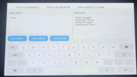
15_udp_tcp_ntp
Hardware Connection
- Connect the board to the computer using a USB cable
Code
15_udp_tcp_ntp.ino
void setup() {
    static esp_lcd_panel_handle_t panel_handle = NULL;
    static esp_lcd_touch_handle_t tp_handle = NULL;

    Serial.begin(115200);
    DEV_I2C_Init();
    IO_EXTENSION_Init();

    // Initialize the GT911 touch screen controller
    tp_handle = touch_gt911_init(DEV_I2C_Get_Bus_Device());

    // Initialize the Waveshare ESP32-S3 RGB LCD hardware
    panel_handle = waveshare_esp32_s3_rgb_lcd_init();

    // Turn on the LCD backlight
    wavesahre_rgb_lcd_bl_on();

    // Initialize LVGL with the panel and touch handles
    ESP_ERROR_CHECK(lvgl_port_init(panel_handle, tp_handle));

    Serial.println("Display UI");

    // Lock the mutex because LVGL APIs are not thread-safe
    if (lvgl_port_lock(-1)) {
         ui_init();
         ui_log("System Initialized. Waiting for WiFi...");
         lvgl_port_unlock();
    }

    // Auto-connect task
    xTaskCreate(wifi_connect_task, "WiFiConnect", 8192, NULL, 3, &ntpTaskHandle);
}

void loop() {
  // Update time
  struct tm timeinfo;
  if (WiFi.status() == WL_CONNECTED && getLocalTime(&timeinfo)) {
    char buf[64];
    strftime(buf, sizeof(buf), "%Y-%m-%d %H:%M:%S", &timeinfo);
    if (lvgl_port_lock(100)) {
      lv_label_set_text_fmt(label_time, "Time: %s", buf);
      lvgl_port_unlock();
    }
  }
  delay(1000);
}
Code Analysis
-
setup():- Initializes the serial port, I2C bus, I/O expansion chip, touchscreen, and LCD hardware, and initializes the LVGL graphics library. Then calls
ui_init()to load the user interface and creates thewifi_connect_tasktask to handle background network connection and time synchronization.
- Initializes the serial port, I2C bus, I/O expansion chip, touchscreen, and LCD hardware, and initializes the LVGL graphics library. Then calls
-
loop():- Periodically fetches the system's local time and uses
lvgl_port_lockto ensure thread-safe updating of the time display label on the screen.
- Periodically fetches the system's local time and uses
-
wifi_connect_task():- Responsible for connecting to the Wi-Fi network and synchronizing the system clock via an NTP server once the connection is successful.
Operation Result
-
After successful flashing, the screen displays system initialization information. After a successful network connection, it will retrieve and continuously update the display with the current date and time via NTP.