LED Strip
The core logic of this tutorial applies to all ESP32 boards, but all the operation steps are explained using the example of the Waveshare ESP32-S3-Zero mini development board. If you are using a development board of another model, please modify the corresponding settings according to the actual situation.
Project Introduction
This project demonstrates a program that controls a WS2812 programmable LED strip using a potentiometer. By rotating the potentiometer, you can change the strip's display effect in real-time: the strip will sequentially go through three stages of color changes (Yellow → Green → Red), and the number of lit LEDs will gradually increase with the rotation, creating a smooth visual gradient effect.
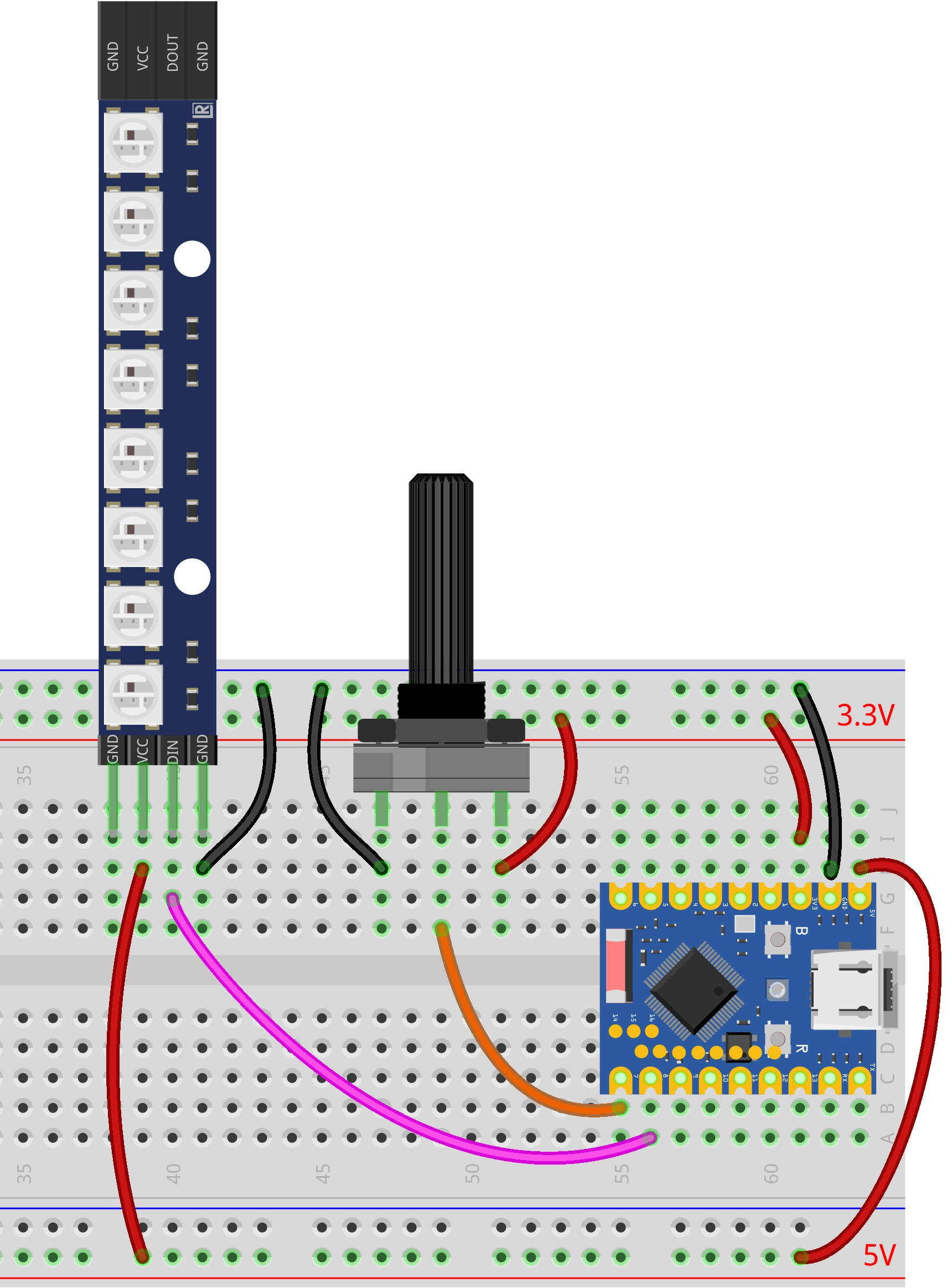
Hardware Connection
Components required:
- WS2812 LED strip * 1
- Potentiometer * 1
- Breadboard * 1
- Wires
- ESP32 development board
Connect the circuit according to the wiring diagram below:
ESP32-S3-Zero Pinout Diagram

Code Implementation
import time
from machine import Pin, ADC
import neopixel

# --- Configuration Parameters ---
POT_PIN_NUM = 7   # Potentiometer pin
NEO_PIN_NUM = 8   # WS2812 pin
NUM_LEDS = 8      # Number of LEDs

# --- Color Definitions (R, G, B) ---
COLOR_YELLOW = (255, 255, 0)
COLOR_GREEN  = (0, 255, 0)
COLOR_RED    = (255, 0, 0)
COLOR_OFF    = (0, 0, 0)

# Initialize WS2812 LED strip
np = neopixel.NeoPixel(Pin(NEO_PIN_NUM), NUM_LEDS)

# Initialize potentiometer (ADC)
pot = ADC(Pin(POT_PIN_NUM))

def update_leds(adc_val):
    """
    Update LED states based on the ADC value
    adc_val: 0 - 65535
    """
    # Map 0-65535 to 0-24 (3 stages * 8 LEDs)
    total_steps = 3 * NUM_LEDS
    position = int((adc_val / 65535) * total_steps)

    # Cap the maximum value to prevent overflow
    if position > total_steps:
        position = total_steps

    for i in range(NUM_LEDS):
        # Logic judgment: Priority from high to low (Red -> Green -> Yellow)

        # Stage 3: Red overlay (when progress exceeds 16 + LED index)
        if position > (2 * NUM_LEDS + i):
            np[i] = COLOR_RED

        # Stage 2: Green overlay (when progress exceeds 8 + LED index)
        elif position > (1 * NUM_LEDS + i):
            np[i] = COLOR_GREEN

        # Stage 1: Yellow lights up (when progress exceeds LED index)
        elif position > i:
            np[i] = COLOR_YELLOW

        # Otherwise: Turn off
        else:
            np[i] = COLOR_OFF

    # Write data to the LED strip
    np.write()

# --- Main Program ---
print("System started: Potentiometer controlling WS2812")

while True:
    try:
        # Read potentiometer analog value (16-bit unsigned integer: 0 - 65535)
        val = pot.read_u16()

        # Update the lighting
        update_leds(val)

        # Simple delay to prevent overly fast refreshing
        time.sleep_ms(50)

    except KeyboardInterrupt:
        # Turn off all LEDs when Ctrl+C is pressed
        for i in range(NUM_LEDS):
            np[i] = COLOR_OFF
        np.write()
        print("Program stopped")
        break
Code Analysis
-
Import Libraries: The
machinelibrary is used for hardware control (ADC and GPIO), theneopixellibrary is used for controlling the WS2812 LED strip, and thetimelibrary is used for implementing delays. The ESP32 MicroPython firmware includes theneopixellibrary by default; no manual installation is required. -
Configuration Parameters: The beginning of the program defines the potentiometer pin number, the WS2812 pin number, and the number of LEDs. Centralizing these parameters facilitates quick adjustments based on actual needs.
# --- Configuration Parameters ---POT_PIN_NUM = 7 # Potentiometer pinNEO_PIN_NUM = 8 # WS2812 pinNUM_LEDS = 8 # Number of LEDs -
Color Definitions: The program defines four colors (Yellow, Green, Red, Off) in RGB triple format, where each value ranges from 0-255. This pre-defined approach makes the code clearer and more readable.
# --- Color Definitions (R, G, B) ---COLOR_YELLOW = (255, 255, 0)COLOR_GREEN = (0, 255, 0)COLOR_RED = (255, 0, 0)COLOR_OFF = (0, 0, 0) -
Hardware Initialization:
- Use
neopixel.NeoPixel()to initialize the WS2812 LED strip. The first parameter is the GPIO pin object, and the second is the number of LEDs. - Use
machine.ADC()to initialize the potentiometer for analog input.
# Initialize WS2812 LED stripnp = neopixel.NeoPixel(Pin(NEO_PIN_NUM), NUM_LEDS)# Initialize potentiometer (ADC)pot = ADC(Pin(POT_PIN_NUM)) - Use
-
Core Function
update_leds(): Updates the display state of the LED strip based on the potentiometer's ADC value.-
Parameter Mapping: Maps the ADC range of 0-65535 to 0-24 (3 stages × 8 LEDs), representing the entire display progress.
# Map 0-65535 to 0-24 (3 stages * 8 LEDs)total_steps = 3 * NUM_LEDSposition = int((adc_val / 65535) * total_steps) -
LED-by-LED Judgment: Iterates through each LED, determining the color it should display based on the current
positionvalue. The judgment logic follows a priority order from high to low (Red → Green → Yellow), ensuring correct color layering:for i in range(NUM_LEDS):# Stage 3: Red overlay (when progress exceeds 16 + LED index)if position > (2 * NUM_LEDS + i):np[i] = COLOR_RED# Stage 2: Green overlay (when progress exceeds 8 + LED index)elif position > (1 * NUM_LEDS + i):np[i] = COLOR_GREEN# Stage 1: Yellow lights up (when progress exceeds LED index)elif position > i:np[i] = COLOR_YELLOW# Otherwise: Turn offelse:np[i] = COLOR_OFF -
Data Writing: Calls
np.write()to send the color data to the WS2812 LED strip. WS2812 uses a single-wire serial communication protocol, so this method must be called for the settings to take effect.
-
-
Main Loop Logic: The program performs the following operations in an infinite loop
while True:- Read Potentiometer: Uses
pot.read_u16()to read a 16-bit unsigned integer (range 0-65535). - Update LED Strip: Calls the
update_leds()function to update the strip's display based on the read value. - Delay Control: Uses
time.sleep_ms(50)to implement a 50-millisecond delay, preventing flickering or resource waste caused by overly fast refreshing.
- Read Potentiometer: Uses
-
Exception Handling: Uses a
try...exceptstructure to enhance program stability.except KeyboardInterrupt: Catches user interrupt signals (like Ctrl+C) and turns off all LEDs before exiting, ensuring the hardware is left in a safe state.