Progress Bar
The core logic of this tutorial applies to all ESP32 boards, but all the operation steps are explained using the example of the Waveshare ESP32-S3-Zero mini development board. If you are using a development board of another model, please modify the corresponding settings according to the actual situation.
Project Introduction
This project demonstrates an interactive progress bar display system. It reads the analog signal from a potentiometer using the ESP32 and displays the progress in real-time on a Waveshare 1.5inch OLED display. The program offers two display modes: a horizontal progress bar and a semi-circular gauge. Users can observe changes in the progress value by rotating the potentiometer.
Hardware Connection
Components required:
- Waveshare 1.5inch OLED Module * 1
- Potentiometer * 1
- Breadboard * 1
- Wires
- ESP32 development board
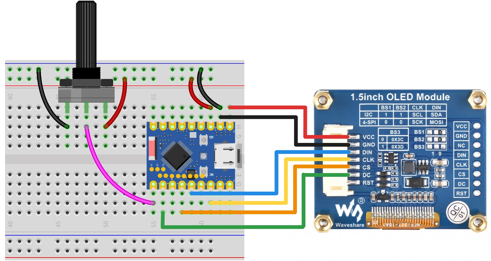
Connect the circuit according to the wiring diagram below:
ESP32-S3-Zero Pinout Diagram

The following uses the SPI interface to connect the OLED display. This screen also supports I2C, controlled via BS1 and BS2. If using I2C mode, please refer to the wiring method in Section 7 I2C Communication.
| ESP32 pin | OLED module | Description |
|---|---|---|
| GPIO 13 | SCK | SPI clock line |
| GPIO 11 | MOSI | SPI data output |
| GPIO 10 | CS | Chip select signal |
| GPIO 8 | DC | Data/command select |
| 5V | VCC | Power positive terminal |
| GND | GND | Power negative terminal |
Code Implementation
This code example requires the ssd1327.py driver library, which is based on the micropython-ssd1327 project by community developer mcauser.
Download link: micropython-ssd1327-master.zip
Please upload the ssd1327.py file from this library to the root directory of your development board.
import time
import math
from machine import Pin, SPI, ADC
import ssd1327

# SPI Pin Configuration
SCK_PIN = 13
MOSI_PIN = 11
CS_PIN = 10
DC_PIN = 8
RST_PIN = 9

# Potentiometer Pin
POT_PIN = 7

# Initialize SPI
spi = SPI(1, baudrate=10000000, sck=Pin(SCK_PIN), mosi=Pin(MOSI_PIN))
# Initialize OLED
oled = ssd1327.SSD1327_SPI(128, 128, spi, dc=Pin(DC_PIN), res=Pin(RST_PIN), cs=Pin(CS_PIN))

# If using I2C, uncomment the code below
# from machine import I2C
# SDA_PIN = 2
# SCL_PIN = 1
# I2C_ADDR = 0x3d
# i2c = I2C(0, scl=Pin(SCL_PIN), sda=Pin(SDA_PIN), freq=400000)
# oled = ssd1327.SSD1327_I2C(128, 128, i2c, I2C_ADDR)

# Initialize ADC
adc = ADC(Pin(POT_PIN))

def get_percentage():
    """Read potentiometer and return an integer 0-100"""
    val = adc.read_u16() # 0-65535
    percent = int((val / 65535) * 100)
    return max(0, min(100, percent))

# Effect Function 1: Horizontal Progress Bar
def show_horizontal_bar(oled, percent):
    """
    Draw a horizontal progress bar
    """
    oled.fill(0) # Clear the buffer

    # Layout parameters
    bar_x = 10
    bar_y = 55
    bar_w = 108
    bar_h = 18

    # 1. Draw the outer frame (using gray, color value 6)
    # Note: Use framebuf.rect
    oled.framebuf.rect(bar_x, bar_y, bar_w, bar_h, 6)

    # 2. Draw the inner fill (using bright white, color value 15)
    # Calculate fill width, reserve 2-pixel margins
    inner_max_w = bar_w - 4
    fill_w = int((percent / 100) * inner_max_w)

    if fill_w > 0:
        oled.framebuf.fill_rect(bar_x + 2, bar_y + 2, fill_w, bar_h - 4, 15)

    # 3. Draw text information
    oled.text("Progress", 32, 35, 8) # Title

    p_str = f"{percent}%"
    # Simple center calculation: screen width 128, assume character width 8
    text_x = 64 - (len(p_str) * 4)
    oled.text(p_str, text_x, 80, 15) # Value

    oled.show() # Refresh display

# Effect Function 2: Semi-circular Gauge
def show_gauge(oled, percent):
    """
    Draw a semi-circular gauge
    """
    oled.fill(0) # Clear the buffer

    # Gauge parameters
    cx, cy = 64, 105  # Center position (centered at the bottom of the screen)
    radius = 55       # Radius
    pointer_len = 48  # Pointer length

    # 1. Draw scale lines (simulate a semicircle)
    # Angle range: 180 degrees (left) -> 0 degrees (right)
    for i in range(0, 11): # 0 to 10, total of 11 major ticks
        angle = 180 - (i * 18)
        rad = math.radians(angle)

        # Outer point
        x1 = int(cx + math.cos(rad) * radius)
        y1 = int(cy - math.sin(rad) * radius)

        # Inner point (tick length 5)
        x2 = int(cx + math.cos(rad) * (radius - 6))
        y2 = int(cy - math.sin(rad) * (radius - 6))

        oled.line(x1, y1, x2, y2, 6) # Color 6 (gray)

    # 2. Draw pointer
    # Calculate angle for the current value
    current_angle = 180 - (percent / 100 * 180)
    current_rad = math.radians(current_angle)

    px = int(cx + math.cos(current_rad) * pointer_len)
    py = int(cy - math.sin(current_rad) * pointer_len)

    oled.line(cx, cy, px, py, 15) # Color 15 (bright)

    # 3. Draw center decoration
    oled.framebuf.fill_rect(cx-2, cy-2, 5, 5, 15)

    # 4. Bottom text
    oled.text(f"{percent}", 56, 110, 15)
    oled.text("GAUGE", 44, 10, 8)

    oled.show() # Refresh display

# ================= Main Loop =================

print("Started.")

while True:
    # Read data
    val = get_percentage()

    # Select display mode (uncomment the one you need)

    # Mode A: Horizontal progress bar
    show_horizontal_bar(oled, val)

    # Mode B: Semi-circular gauge
    # show_gauge(oled, val)

    # Simple delay to prevent overly fast refreshing
    time.sleep(0.05)
Code Analysis
-
Import Libraries: The
machinelibrary is used for hardware control (SPI, I2C, ADC, and GPIO), thessd1327library is used to drive the 1.5inch OLED display, thetimelibrary is used for delays, and themathlibrary is used for trigonometric calculations when drawing the gauge. -
Pin Configuration: The beginning of the program defines the pin numbers for SPI communication and the ADC pin for the potentiometer. Centralizing these parameters facilitates quick adjustments based on actual needs.
# SPI Pin ConfigurationSCK_PIN = 13MOSI_PIN = 11CS_PIN = 10DC_PIN = 8RST_PIN = 9# Potentiometer PinPOT_PIN = 7 -
Hardware Initialization:
- SPI Method (Default):
- Use
machine.SPI()to initialize the SPI bus, setting the baud rate to 10MHz. - Use
ssd1327.SSD1327_SPI()to initialize the OLED, passing the resolution, SPI object, and control pins.
- Use
- I2C Method (Optional):
- I2C initialization code is reserved in the program (commented by default). If using a screen with an I2C interface, you need to uncomment the relevant code.
- Use
machine.I2C()to initialize the I2C bus, and usessd1327.SSD1327_I2C()to initialize the OLED, specifying the I2C address (usually0x3d).
- ADC Initialization: Use
machine.ADC()to initialize the potentiometer for analog input.
# Initialize SPI (Default)spi = SPI(1, baudrate=10000000, sck=Pin(SCK_PIN), mosi=Pin(MOSI_PIN))oled = ssd1327.SSD1327_SPI(128, 128, spi, dc=Pin(DC_PIN), res=Pin(RST_PIN), cs=Pin(CS_PIN))# Initialize I2C (Optional)# i2c = I2C(0, scl=Pin(SCL_PIN), sda=Pin(SDA_PIN), freq=400000)# oled = ssd1327.SSD1327_I2C(128, 128, i2c, I2C_ADDR)# Initialize ADCadc = ADC(Pin(POT_PIN)) - SPI Method (Default):
-
Helper Function
get_percentage(): Reads the ADC value from the potentiometer and converts it to a percentage from 0-100.- Use
adc.read_u16()to read a 16-bit unsigned integer (range 0-65535). - Map the read value to the range 0-100 and use
max()andmin()to ensure the result is within the valid range.
def get_percentage():"""Read potentiometer and return an integer 0-100"""val = adc.read_u16() # 0-65535percent = int((val / 65535) * 100)return max(0, min(100, percent)) - Use
-
Effect Function 1:
show_horizontal_bar(): Draws a horizontal progress bar.- Clear Screen: Call
oled.fill(0)to clear the display buffer. - Draw Outer Frame: Use
oled.framebuf.rect()to draw the progress bar border with a color value of 6 (gray). - Calculate Fill Width: Calculate the width of the inner fill bar based on the percentage, reserving a 2-pixel margin to avoid overlapping the frame.
- Draw Fill: Use
oled.framebuf.fill_rect()to draw the filled portion with a color value of 15 (bright white). - Display Text: Display the title "Progress" above the bar and the percentage value below.
- Refresh Display: Call
oled.show()to send the buffer content to the screen.
- Clear Screen: Call
-
Effect Function 2:
show_gauge(): Draws a semi-circular gauge.-
Clear Screen: Call
oled.fill(0)to clear the display buffer. -
Draw Scale Lines: Draw 11 scale lines (0% to 100%, every 10%) through a loop. Use trigonometric functions to calculate the start and end coordinates for each line, with an angle range from 180° (left) to 0° (right).
for i in range(0, 11): # 0 to 10, total of 11 major ticksangle = 180 - (i * 18)rad = math.radians(angle) -
Draw Pointer: Calculate the pointer angle based on the percentage, and use
oled.line()to draw a line from the center to the pointer's end with a color value of 15 (bright).current_angle = 180 - (percent / 100 * 180)current_rad = math.radians(current_angle)px = int(cx + math.cos(current_rad) * pointer_len)py = int(cy - math.sin(current_rad) * pointer_len)oled.line(cx, cy, px, py, 15) -
Draw Center Decoration: Draw a small square at the center point as a visual focus.
-
Display Text: Display the percentage value and the title "GAUGE" at the bottom.
-
-
Main Loop Logic: The program performs the following operations in an infinite loop
while True:- Read Data: Call
get_percentage()to get the potentiometer's percentage value. - Select Display Mode: The program provides two display modes (horizontal progress bar and semi-circular gauge), switched by commenting/uncommenting.
- Delay Control: Uses
time.sleep(0.05)to implement a 50-millisecond delay, preventing flickering or resource waste caused by overly fast refreshing.
while True:val = get_percentage()# Mode A: Horizontal progress barshow_horizontal_bar(oled, val)# Mode B: Semi-circular gauge# show_gauge(oled, val)time.sleep(0.05) - Read Data: Call