LED Strip
The core logic of this tutorial applies to all ESP32 development boards. However, all operational steps are explained using the Waveshare ESP32-S3-Zero Mini Development Board as an example. If you are using a different model of development board, please modify the relevant settings according to your actual situation.
Project Introduction
This project demonstrates a program that controls a WS2812 programmable LED strip using a potentiometer. By rotating the potentiometer, you can change the strip's display effect in real time: the strip will cycle through three color stages (Yellow → Green → Red), and the number of lit LEDs will gradually increase as you rotate the potentiometer, creating a smooth visual gradient.
Hardware Connection
The components required are:
- WS2812 LED strip * 1
- Potentiometer * 1
- Breadboard * 1
- Wire
- ESP32 development board
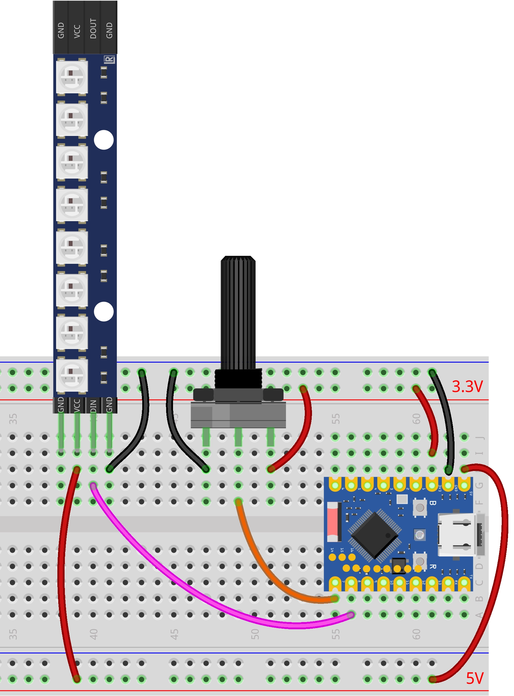
Connect the circuit according to the wiring diagram below:
ESP32-S3-Zero Pinout Diagram

Code Implementation
This demo depends on the "FastLED" library. Please search for and install the "FastLED" library via the Library Manager in Arduino IDE.
For installation instructions, please refer to: Arduino library manager tutorial.
/*
  Potentiometer controls WS2812 LED strip

  Reads the analog value from a potentiometer and maps it to the WS2812 LED strip.
  As the value increases, the lights turn on sequentially (Yellow -> Green -> Red).

  Circuit Connection:
  * Potentiometer connected to Pin 7
  * WS2812 LED Strip data line connected to Pin 8

  Wulu (Waveshare Team)
*/

#include <FastLED.h>

// --- Constant Definitions ---
const int potPin = 7;       // Potentiometer pin
const int ledPin = 8;       // WS2812 data pin
const int numLeds = 8;      // Number of LEDs
const int brightness = 50;  // Brightness level
// Define the LED array
CRGB leds[numLeds];

void setup() {
  Serial.begin(115200);
  Serial.println("Potentiometer Controls WS2812");

  // Initialize potentiometer pin
  pinMode(potPin, INPUT);

  // Initialize FastLED
  FastLED.addLeds<WS2812B, ledPin, GRB>(leds, numLeds).setCorrection(TypicalLEDStrip);
  FastLED.setBrightness(brightness);
  FastLED.clear();
  FastLED.show();
}

void loop() {
  // Read the analog value from the potentiometer
  int analogValue = analogRead(potPin);

  // Update the LED strip
  updateLeds(analogValue);

  // Simple delay to prevent excessive refresh rate
  delay(50);
}

// Helper function placed after loop
void updateLeds(int analogValue) {
  // Map the 0-4095 range to 0-24 (3 phases * 8 LEDs)
  int totalSteps = 3 * numLeds;

  // Use the map function for mapping
  long position = map(analogValue, 0, 4095, 0, totalSteps);

  // Limit the maximum value to prevent overflow
  if (position > totalSteps) {
    position = totalSteps;
  }

  // Iterate through all LEDs
  for (int i = 0; i < numLeds; i++) {
    // Logic decision: priority from high to low (Red -> Green -> Yellow)

    // Third phase: Red overwrite (when progress exceeds 16 + LED index)
    if (position > (2 * numLeds + i)) {
      leds[i] = CRGB::Red;
    }
    // Second phase: Green overwrite (when progress exceeds 8 + LED index)
    else if (position > (1 * numLeds + i)) {
      leds[i] = CRGB::Green;
    }
    // First phase: Yellow turn-on (when progress exceeds LED index)
    else if (position > i) {
      leds[i] = CRGB::Yellow;
    }
    // Otherwise: Turn off
    else {
      leds[i] = CRGB::Black;
    }
  }

  // Send data to the LED strip
  FastLED.show();
}
Code Analysis
-
Library Inclusion: Includes the
FastLEDlibrary for controlling the WS2812 LED strip. This is a powerful and efficient library for LED control.tipThis demo depends on the "FastLED" library. Please search for and install the "FastLED" library via the Library Manager in Arduino IDE.
For installation instructions, please refer to: Arduino library manager tutorial.
-
Configuration Parameters & Global Variables: Uses
constconstants to define the potentiometer pin, WS2812 data pin, number of LEDs, and brightness.const int potPin = 7; // Potentiometer pin
const int ledPin = 8; // WS2812 data pin
const int numLeds = 8; // Number of LEDs
const int brightness = 50; // Brightness -
Object Initialization:
- Defines a
CRGBtype arrayledsto store the color data for each LED.
CRGB leds[numLeds]; - Defines a
-
setup()Function:- Initializes serial communication.
- Sets the potentiometer pin to input mode.
- Initializes FastLED: Uses
FastLED.addLedsto configure the LED strip parameters (type, pin, color order, array address, count). Color correction can also be applied.FastLED.addLeds<WS2812B, ledPin, GRB>(leds, numLeds)– without color correction.FastLED.addLeds<WS2812B, ledPin, GRB>(leds, numLeds).setCorrection(TypicalLEDStrip);– with color correction for more natural and accurate colors.
FastLED.setBrightness(brightness)sets the global brightness.FastLED.clear()和FastLED.show()ensure the LED strip is off at startup.
-
updateLeds()Function:- Mapping: Uses the
map()function to map the ADC reading (0-4095) to the total number of steps (0-24). - Logic Decision: Iterates through each LED, determining its color based on the current progress
position. - Setting Color: Directly assigns predefined colors (e.g.,
CRGB::Red,CRGB::Green,CRGB::Yellow,CRGB::Black) toleds[i]. - Updating Display: Calls
FastLED.show()to send the color data from the array to the LED strip.
- Mapping: Uses the
-
loop()Function:- Uses
analogRead()to read the voltage value from the potentiometer. - Calls
updateLeds()to update the state of the LED strip. - Uses
delay(50)for a simple delay.
- Uses