Progress Bar
The core logic of this tutorial applies to all ESP32 development boards. However, all operational steps are explained using the Waveshare ESP32-S3-Zero Mini Development Board as an example. If you are using a different model of development board, please modify the relevant settings according to your actual situation.
Project Introduction
This project demonstrates an interactive progress bar display system. It uses an ESP32 to read analog signals from a potentiometer and displays the progress in real-time on a Waveshare 1.5inch OLED display. The program provides two display modes: a horizontal progress bar and a semi-circular gauge. Users can rotate the potentiometer to observe changes in the progress value.
Hardware Connection
The components required are:
- Waveshare 1.5inch OLED Module * 1
- Potentiometer * 1
- Breadboard * 1
- Wire
- ESP32 development board
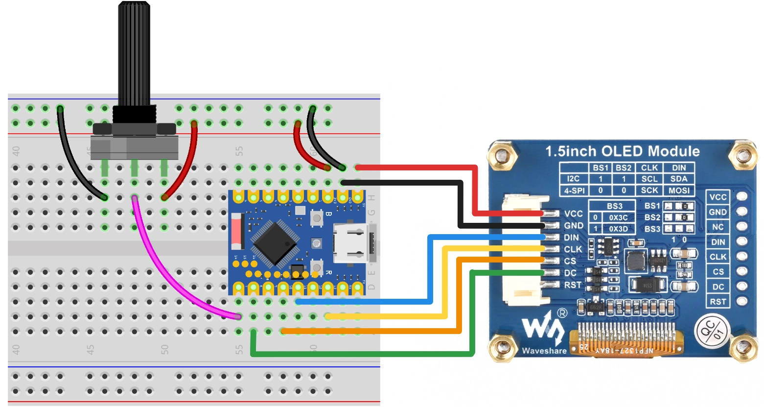
Connect the circuit according to the wiring diagram below:
ESP32-S3-Zero Pinout Diagram

This example uses the SPI interface to connect to the OLED display. This screen also supports I2C, controlled via BS1 and BS2. If you are using I2C mode, please refer to the wiring method described in Section 7 I2C Communication.
| ESP32 Pin | OLED Module | Description |
|---|---|---|
| GPIO 13 | SCK | SPI Clock Line |
| GPIO 11 | MOSI | SPI Data Output |
| GPIO 10 | CS | Chip Select Signal |
| GPIO 8 | DC | Data/Command Select |
| 5V | VCC | Power Positive |
| GND | GND | Power Ground |
Code Implementation
This code example depends on the Adafruit SSD1327 library. Please search for and install "Adafruit SSD1327" and its dependency "Adafruit GFX Library" in the Arduino IDE Library Manager.
/*
  Progress Bar

  This example demonstrates how to draw on a 128x128 OLED screen:
  1. Horizontal Progress Bar
  2. Semi-circular Gauge

  - OLED SCK  -> GPIO 13
  - OLED MOSI -> GPIO 11
  - OLED CS   -> GPIO 10
  - OLED DC   -> GPIO 8
  - Potentiometer -> GPIO 7

  Wulu (Waveshare Team)
*/

#include <Adafruit_SSD1327.h>

// SPI Pin Configuration
const int SCK_PIN = 13;
const int MOSI_PIN = 11;
const int CS_PIN = 10;
const int DC_PIN = 8;

// Potentiometer Pin
const int POT_PIN = 7;

// Create display object (SPI)
// 128x128 resolution
Adafruit_SSD1327 display(128, 128, &SPI, DC_PIN, -1, CS_PIN);

// If using I2C, please use the following constructor (I2C address needs to be confirmed, usually 0x3D)
// const int SDA_PIN = 2;
// const int SCL_PIN = 1;
// Adafruit_SSD1327 display(128, 128, &Wire, -1); // -1 indicates no reset pin

void setup() {
  Serial.begin(115200);

  // Initialize potentiometer pin
  pinMode(POT_PIN, INPUT);

  // Wire.begin(SDA_PIN, SCL_PIN);

  // Initialize OLED (I2C)
  // if (!display.begin(0x3D)) {
  //   Serial.println("Unable to initialize OLED");
  //   while (1) yield();
  // }

  SPI.begin(SCK_PIN, -1, MOSI_PIN, CS_PIN);

  // Initialize OLED
  if (!display.begin()) {
    Serial.println("Unable to initialize OLED");
    while (1) yield();
  }

  display.setTextSize(1);
  display.setTextColor(SSD1327_WHITE);
  // Adjust rotation as needed
  display.setRotation(0);
}

void loop() {
  // Read data
  int val = getPercentage();

  // Select display mode (uncomment the one you need)

  // Mode A: Horizontal Progress Bar
  showHorizontalBar(val);

  // Mode B: Semi-circular Gauge
  // showGauge(val);

  // Simple delay to prevent excessive refresh rate
  delay(50);
}

int getPercentage() {
  // Read potentiometer and return an integer between 0-100
  // ESP32 defaults to 12-bit (0-4095)
  int val = analogRead(POT_PIN);
  int percent = map(val, 0, 4095, 0, 100);
  return constrain(percent, 0, 100);
}

// Effect Function 1: Horizontal Progress Bar
void showHorizontalBar(int percent) {
  // Clear the buffer
  display.clearDisplay();

  // Layout parameters
  int barX = 10;
  int barY = 55;
  int barWidth = 108;
  int barHeight = 18;

  // 1. Draw the outer frame
  // SSD1327 supports grayscale, but the GFX library's basic drawing functions typically use monochrome logic.
  // Here we simply use WHITE.
  display.drawRect(barX, barY, barWidth, barHeight, SSD1327_WHITE);

  // 2. Draw the inner fill
  // Calculate the fill width, leaving a 2-pixel margin
  int innerMaxWidth = barWidth - 4;
  int fillWidth = (int)((percent / 100.0) * innerMaxWidth);

  if (fillWidth > 0) {
    display.fillRect(barX + 2, barY + 2, fillWidth, barHeight - 4, SSD1327_WHITE);
  }

  // 3. Draw text information
  display.setCursor(32, 35);
  display.print("Progress");

  // Simple centering
  display.setCursor(50, 80);
  display.print(percent);
  display.print("%");

  // Refresh the display
  display.display();
}

// Effect Function 2: Semi-circular Gauge
void showGauge(int percent) {
  display.clearDisplay();

  // Gauge parameters
  int centerX = 64;
  int centerY = 105;
  int radius = 55;
  int pointerLen = 48;

  // 1. Draw tick marks (simulating a semi-circle)
  // Angle range: 180 degrees (left) -> 0 degrees (right)
  for (int i = 0; i <= 10; i++) {
    float angle = 180 - (i * 18);
    float rad = angle * PI / 180.0;

    // Outer point
    int x1 = centerX + (int)(cos(rad) * radius);
    int y1 = centerY - (int)(sin(rad) * radius);

    // Inner point (tick length 5)
    int x2 = centerX + (int)(cos(rad) * (radius - 6));
    int y2 = centerY - (int)(sin(rad) * (radius - 6));

    display.drawLine(x1, y1, x2, y2, SSD1327_WHITE);
  }

  // 2. Draw the pointer
  float currentAngle = 180 - (percent / 100.0 * 180);
  float currentRad = currentAngle * PI / 180.0;

  int needleX = centerX + (int)(cos(currentRad) * pointerLen);
  int needleY = centerY - (int)(sin(currentRad) * pointerLen);

  display.drawLine(centerX, centerY, needleX, needleY, SSD1327_WHITE);

  // 3. Draw center decoration
  display.fillRect(centerX - 2, centerY - 2, 5, 5, SSD1327_WHITE);

  // 4. Text
  display.setCursor(58, 110);
  display.print(percent);
  display.setCursor(50, 10);
  display.print("GAUGE");

  display.display();
}
Code Analysis
-
Library Import: Includes the
Adafruit_SSD1327.hlibrary, which depends on theAdafruit_GFXlibrary to provide graphics drawing functionality. -
Pin Configuration & Initialization:
- Uses
const intto define SPI pins and the potentiometer pin. - Creates an
Adafruit_SSD1327object nameddisplay, specifying the resolution (128x128) and SPI control pins. Note that the reset pin is set to -1, indicating the hardware reset pin is not used. - In
setup(), first callsSPI.begin(...)to initialize the SPI bus, then callsdisplay.begin()to initialize the screen.
// Initialize OLED (SPI)
Adafruit_SSD1327 display(128, 128, &SPI, DC_PIN, -1, CS_PIN);

void setup() {
  // ...
  SPI.begin(SCK_PIN, -1, MOSI_PIN, CS_PIN);
  if (!display.begin()) {
    // Handle initialization failure
  }
  // ...
} - Uses
-
Helper Function
getPercentage():- Uses
analogRead(POT_PIN)to read the analog value from the potentiometer (ESP32 defaults to 12-bit resolution, range 0-4095). - Uses the
map()function to map the range 0-4095 to 0-100. - Uses
constrain()to ensure the result is strictly within the 0-100 range.
- Uses
-
Effect Function 1:
showHorizontalBar():display.clearDisplay(): Clears the screen buffer.display.drawRect(): Draws the outer frame of the progress bar.display.fillRect(): Calculates the width based on the percentage and draws a filled rectangle as the progress bar fill.display.setCursor()和display.print(): Sets the cursor position and prints text.display.display(): Sends the buffer content to the OLED display.
-
Effect Function 2:
showGauge():- Uses trigonometric functions
cos()andsin()(requires including<math.h>, which is supported by default in the Arduino environment) to calculate the coordinates of tick marks and the pointer. display.drawLine(): Draws the tick marks and the pointer.- The logic is similar to the Python version, converting angles to radians for calculation.
- Uses trigonometric functions
-
Main Loop
loop():- Continuously reads the potentiometer value.
- Calls the display function to update the screen.
delay(50): Adds a brief delay to avoid excessive refresh rate.